Jeep Grand Cherokee WK. Manual - part 956
P0335-CRANKSHAFT POSITION SENSOR CIRCUIT (CONTINUED)
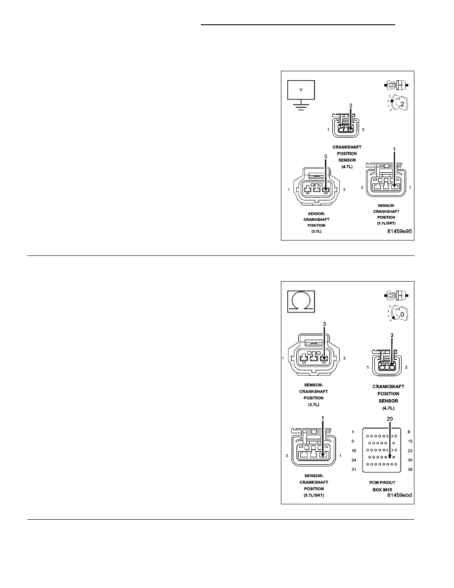
10.
(F855) 5-VOLT SUPPLY CIRCUIT SHORTED TO BATTERY VOLTAGE
Turn the ignition off.
Disconnect the C2 PCM harness connector.
Ignition on, engine not running.
Measure the voltage on the (F855) 5-volt Supply circuit in the CKP
Sensor harness connector.
Is the voltage above 0 volts?
Yes
>> Repair the short to battery voltage in the (F855) 5-volt
Supply circuit.
Perform the POWERTRAIN VERIFICATION TEST. (Refer
to 9 - ENGINE - STANDARD PROCEDURE)
No
>> Go To 11
11.
(F855) 5-VOLT SUPPLY CIRCUIT OPEN
Turn the ignition off.
CAUTION: Do not probe the PCM harness connectors. Probing
the PCM harness connectors will damage the PCM terminals
resulting in poor terminal to pin connection. Install Miller Special
Tool #8815 to perform diagnosis.
Measure the resistance of the (F855) 5-volt Supply circuit from the
CKP Sensor harness connector to the appropriate terminal of special
tool #8815.
Is the resistance below 5.0 ohms?
Yes
>> Go To 12
No
>> Repair the open in the (F855) 5-volt Supply circuit.
Perform the POWERTRAIN VERIFICATION TEST. (Refer
to 9 - ENGINE - STANDARD PROCEDURE)
9 - 420
ENGINE ELECTRICAL DIAGNOSTICS
WK