Jeep Grand Cherokee WK. Manual - part 954
P0330-KNOCK SENSOR 2 CIRCUIT (CONTINUED)
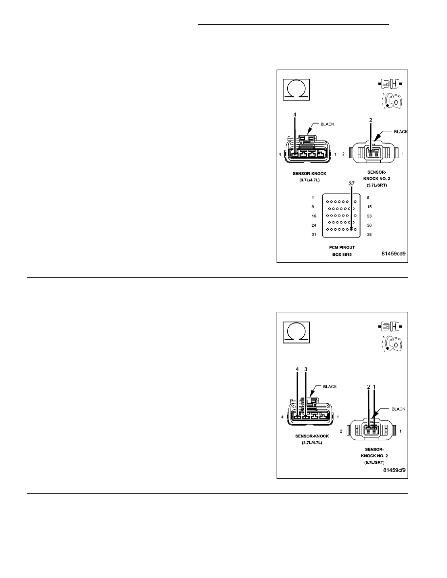
4.
(K924) KNOCK SENSOR NO.2 RETURN CIRCUIT OPEN
Measure the resistance of the (K924) Knock Sensor No.2 Return cir-
cuit from the Knock Sensor harness connector to the appropriate ter-
minal of special tool #8815.
Is the resistance below 5.0 ohms?
Yes
>> Go To 5
No
>> Repair the open in the (K924) Knock Sensor No.2 Return
circuit.
Perform the POWERTRAIN VERIFICATION TEST. (Refer
to 9 - ENGINE - STANDARD PROCEDURE)
5.
(K242) KNOCK SENSOR NO.2 SIGNAL CIRCUIT SHORTED TO THE (K924) KNOCK SENSOR NO.2
RETURN CIRCUIT
Measure the resistance between the (K242) Knock Sensor No.2 Signal
circuit and the (K924) Knock Sensor No.2 Return circuit in the Knock
Sensor harness connector.
Is the resistance below 100 ohms?
Yes
>> Repair the short between the (K242) Knock Sensor No.2
Signal circuit and the (K924) Knock Sensor No.2 Return
circuit.
Perform the POWERTRAIN VERIFICATION TEST. (Refer
to 9 - ENGINE - STANDARD PROCEDURE)
No
>> Go To 6
9 - 412
ENGINE ELECTRICAL DIAGNOSTICS
WK