Jeep Grand Cherokee WK. Manual - part 717
B1415-HFM RIGHT AUDIO OUTPUT CIRCUIT LOW (CONTINUED)
4.
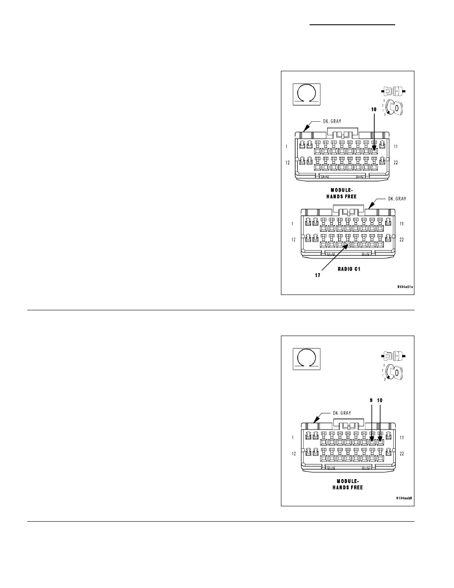
(X795) COMMON AUDIO OUTPUT CIRCUIT OPEN
Measure the resistance of the (X795) Common Audio Output circuit
between the HFM connector and the radio connector.
Is the resistance below 5.0 ohms?
Yes
>> Go To 5
No
>> Repair the (X795) Common Audio Output circuit for an
open.
Perform BODY VERIFICATION TEST – VER 1. (Refer to 8
- ELECTRICAL/ELECTRONIC CONTROL MODULES -
STANDARD PROCEDURE).
5.
(X704) RIGHT AUDIO OUTPUT CIRCUIT SHORT TO (X795) COMMON AUDIO OUTPUT CIRCUIT
Measure the resistance between the (X704) Right Audio Output circuit
and the (X795) Common Audio Output circuit.
Is the resistance below 5.0 ohms?
Yes
>> Repair the (X704) Right Audio Output circuit for a short to
the (X795) Common Audio Output circuit.
Perform BODY VERIFICATION TEST – VER 1. (Refer to 8
- ELECTRICAL/ELECTRONIC CONTROL MODULES -
STANDARD PROCEDURE).
No
>> Inspect the wiring and connectors for damage or shorted
circuits. If ok, replace and program the Hands Free Mod-
ule in accordance with the service information.
Perform BODY VERIFICATION TEST – VER 1. (Refer to 8
- ELECTRICAL/ELECTRONIC CONTROL MODULES -
STANDARD PROCEDURE).
8T - 14
NAVIGATION/TELECOMMUNICATION - ELECTRICAL DIAGNOSTICS
WK