Jeep Grand Cherokee WK. Manual - part 543


  Index      Jeep     Jeep Grand Cherokee WK - service repair manual 2005 year


Search            


Content   ..  541  542  543  544   ..


Jeep Grand Cherokee WK. Manual - part 543


6. Press the open position on the power sunroof switch and release. The sunroof glass panel should continue travel

to the full open position.

7. Press the close position on the power sunroof switch and release. The sunroof glass panel should continue

travel to the full closed position. This will be considered the first sunroof closed position in a series of five
sunroof closes.

8. Press the open position on the power sunroof switch and release. The sunroof glass panel should move to the

full open position. After the sunroof motor/module has stopped, press the close position on the power sunroof
switch and release. The sunroof glass panel should continue travel to the full closed position. Continue to move
the sunroof glass to the “open” then “closed” position four more times so that the sunroof glass has
moved to the closed position a total of five times starting with the first sunroof close in step 7.

Verify proper EFL calibration by placing a standard pencil at the front of the sunroof and then moving the
sunroof to the full closed position. The sunroof should reverse direction upon contact without damage to
the pencil.

REMOVAL

WARNING: The Excessive Force Limitation (EFL) feature must be calibrated any time a sunroof motor/mod-
ule is replaced with a new component. Failure to perform this procedure could result in vehicle damage
and/or personal injury. (Refer to 8 - ELECTRICAL/POWER TOP/MOTOR - STANDARD PROCEDURE - EXCES-
SIVE FORCE LIMITATION (EFL) CALIBRATION) for the appropriate procedure.

1. Disconnect the battery negative cable.

2. Remove the vehicle headliner, (Refer to 23 - BODY/INTERIOR/HEADLINER - REMOVAL).

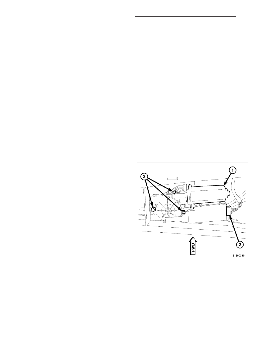
3. Remove the power sunroof motor/module electrical

connector (2).

4. Remove the retaining screws (3) and remove the

motor/module (1) from the vehicle.

INSTALLATION

WARNING: The Excessive Force Limitation (EFL) feature must be calibrated any time a sunroof motor/mod-
ule is replaced with a new component. Failure to perform this procedure could result in vehicle damage
and/or personal injury. (Refer to 8 - ELECTRICAL/POWER TOP/MOTOR - STANDARD PROCEDURE - EXCES-
SIVE FORCE LIMITATION (EFL) CALIBRATION) for the appropriate procedure.

8N - 332

POWER TOP - SUNROOF SERVICE INFO

WK

1. Position the power sunroof motor/module (1) in the

vehicle.

2. Install

the

motor/module

retaining

screws

(3).

Tighten the screws to 4 N·m (35 in. lbs.).

3. Connect the motor/module electrical connector (2).

4. Connect the battery negative cable and move the

sunroof through one open and close cycle to con-
firm proper system operation.

5. Install the vehicle headliner, (Refer to 23 - BODY/

INTERIOR/HEADLINER - INSTALLATION).

6. Perform the sunroof position calibration, (Refer to 8

- ELECTRICAL/POWER TOP/MOTOR - STAN-
DARD

PROCEDURE

-

SUNROOF

POSITION

CALIBRATION).

7. Perform the Excessive Force Limitation (EFL) cali-

bration, (Refer to 8 - ELECTRICAL/POWER TOP/
MOTOR

-

STANDARD

PROCEDURE

-

EXCESSIVE FORCE LIMITATION (EFL) CALIBRA-
TION).

8. Verify proper operation of the power sunroof system.

SWITCH - SUNROOF

DESCRIPTION

The power sunroof switch (3) is a combination push-
button and rocker switch module mounted in the over-
head console. The sunroof switch is a direct contact
unit that is directly wired to the sunroof motor/module
assembly. The sunroof switch performs the following
functions:

Power sunroof open (back of switch pushed)

Power sunroof closed (front of switch pushed)

Power

sunroof

vent

(switch

center

button

pushed)

The power sunroof switch is part of the overhead
console assembly and cannot be replaced sepa-
rately. If the switch is damaged or inoperative the
overhead console must be replaced, (Refer to 8 -
ELECTRICAL/OVERHEAD CONSOLE - REMOVAL).

OPERATION

The power sunroof switch is hard wired to the sunroof motor/module assembly. The switch receives battery current
from the motor/module when the ignition switch is in the RUN and ACCESSORY positions or the vehicle Accessory
Delay System is active. When one of the switch positions is pressed it sends battery current back to the motor/
module, signaling it to move the power sunroof to the appropriate position. The motor/module will perform one of the
following functions:

Power sunroof open (back of switch pushed)

Power sunroof closed (front of switch pushed)

Power sunroof vent (switch center button pushed)

WK

POWER TOP - SUNROOF SERVICE INFO

8N - 333

DIAGNOSIS AND TESTING

SWITCH - POWER SUNROOF

Any diagnosis of the power sunroof system should begin with the use of a scan tool and the proper Diagnostic
Procedures Information. The scan tool can provide confirmation that the Controller Area Network (CAN) Data Bus
circuit is functional, that all of the electronic modules are sending and receiving the proper messages on the CAN
Data Bus, and that the power sunroof motor/module assembly is being sent the proper hard wired output by the
sunroof switch.

For complete circuit diagrams, refer to the appropriate wiring information. The wiring information includes wiring dia-
grams, proper wire and connector repair procedures, details of wire harness routing and retention, connector pin-out
information and location views for the various wire harness connectors, splices and grounds. If completing the
appropriate diagnostic information results in the sunroof switch being inoperative, perform the following test prior to
switch replacement.

1. Disconnect and isolate the battery negative cable.

2. Remove the overhead console, (Refer to 8 - ELEC-

TRICAL/OVERHEAD CONSOLE - REMOVAL).

3. Disconnect the power sunroof switch wire harness

connector.

4. Using an ohmmeter, test the continuity of the

power sunroof switch in each switch position. Refer
to the POWER SUNROOF SWITCH CONTINUITY
TABLE . If OK, inspect the wiring harness and con-
nectors for damage. Use a scan tool and the
proper Diagnostic Procedures Information to com-
plete diagnosis of the power sunroof system. If not
OK, replace the overhead console.

POWER SUNROOF SWITCH CONTINUITY TABLE

SWITCH POSITION

CONTINUITY BETWEEN PINS

OFF

NO CONTINUITY

SUNROOF OPEN

B & D

SUNROOF CLOSED

B & C

SUNROOF VENT

B & A

8N - 334

POWER TOP - SUNROOF SERVICE INFO

WK

POWER WINDOWS - SERVICE INFORMATION

TABLE OF CONTENTS

page

page

POWER WINDOWS - SERVICE INFORMATION

DESCRIPTION

. . . . . . . . . . . . . . . . . . . . . . . . 335

OPERATION

. . . . . . . . . . . . . . . . . . . . . . . . . . 335

DIAGNOSIS AND TESTING

POWER WINDOWS

. . . . . . . . . . . . . . . . . . . 336

MOTOR-WINDOW

DIAGNOSIS AND TESTING

WINDOW MOTOR

. . . . . . . . . . . . . . . . . . . . 337

REMOVAL

. . . . . . . . . . . . . . . . . . . . . . . . . . . . 337

SWITCH-POWER WINDOW

DIAGNOSIS AND TESTING

POWER WINDOW SWITCH

. . . . . . . . . . . . . 337

REMOVAL

. . . . . . . . . . . . . . . . . . . . . . . . . . . . 338

INSTALLATION

. . . . . . . . . . . . . . . . . . . . . . . . 338

POWER WINDOWS - SERVICE INFORMATION

DESCRIPTION

The power window system allows each of the door windows to be raised and lowered electrically by actuating a
switch on the trim panel of each respective door. A master switch on the driver side front door trim panel allows the
driver to raise or lower each of the passenger door windows and to lock out the individual switches on the pas-
senger doors from operation. The power window system receives battery feed through a circuit breaker, only when
the ignition switch is in the On position.

The power window system includes the power window switches on each door trim panel, the circuit breaker, and the
power window motors inside each door.

The power window motor is integral to the power window regulator unit. If the power window motor is inoperative or
damaged, the entire power window regulator unit must be replaced. (Refer to 23 - BODY/DOOR - FRONT/WINDOW
REGULATOR - REMOVAL) or (Refer to 23 - BODY/DOORS - REAR/WINDOW REGULATOR - REMOVAL) for the
window regulator service procedures.

OPERATION

POWER WINDOW SWITCH

The power windows are controlled by a window/lock switch on the trim panel of each front door. Switches in the
driver door window/lock switch allows the driver to control the passenger windows.

The power window switch for the driver side front door window has a second detent position beyond the normal
Down position that provides an automatic one-touch window down feature. This feature is controlled by the window/
lock switch.

The power window switches control the battery and ground feeds to the power window motors. All of the passenger
door power window switches receive their battery and ground feeds through the circuitry of the window/lock switch.
When the power window lockout switch is in the Lock position, the battery feed for the individual passenger door
power window switches is interrupted.

POWER WINDOW MOTOR

A permanent magnet reversible motor moves the window regulator through an integral gearbox mechanism. A pos-
itive and negative battery connection to the two motor terminals will cause the motor to rotate in one direction.
Reversing the current through these same two connections will cause the motor to rotate in the opposite direction.

In addition, each power window motor is equipped with an integral self-resetting circuit breaker to protect the motor
from overloads. The power window motor and gearbox assembly cannot be repaired and, if inoperative or damaged,
the power window regulator must be replaced.

WK

POWER WINDOWS - SERVICE INFORMATION

8N - 335


Content   ..  541  542  543  544   ..