Jeep Grand Cherokee WK. Manual - part 537


  Index      Jeep     Jeep Grand Cherokee WK - service repair manual 2005 year


Search            


Content   ..  535  536  537  538   ..


Jeep Grand Cherokee WK. Manual - part 537


B1841–SUNROOF OPEN SWITCH INPUT CIRCUIT HIGH (CONTINUED)

4.

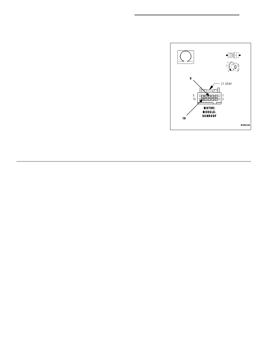
(Q3) SUNROOF OPEN SWITCH SENSE CIRCUIT SHORT TO (Q6) SUNROOF SWITCH SUPPLY CIRCUIT

Turn the ignition off.

Disconnect the A-Pillar connector.

Measure the resistance between the (Q3) Sunroof Open Switch Sense
circuit and the (Q6) Sunroof Switch Supply circuit in the Sunroof
Motor/Module connector.

Is the resistance below 1000.0 ohms?

Yes

>> Repair the (Q3) Sunroof Open Switch Sense circuit for a

short to the (Q6) Sunroof Switch Supply circuit.

Perform BODY VERIFICATION TEST - VER 1. (Refer to 8
- ELECTRICAL/ELECTRONIC CONTROL MODULES -
STANDARD PROCEDURE)

No

>> Replace the Sunroof Motor/Module.

Perform the Sunroof Position Calibration, (Refer to 8 -
ELECTRICAL/POWER TOP/MOTOR - STANDARD PRO-
CEDURE - SUNROOF POSITION CALIBRATION). Per-
form the Excessive Force Limitation Calibration, (Refer to 8 - ELECTRICAL/POWER TOP/MOTOR -
STANDARD PROCEDURE - EXCESSIVE FORCE LIMITATION CALIBRATION).

Perform BODY VERIFICATION TEST - VER 1. (Refer to 8 - ELECTRICAL/ELECTRONIC CONTROL
MODULES - STANDARD PROCEDURE)

8N - 308

POWER TOP - ELECTRICAL DIAGNOSIS

WK

B1844–SUNROOF CLOSE SWITCH INPUT CIRCUIT HIGH

WK

POWER TOP - ELECTRICAL DIAGNOSIS

8N - 309

B1844–SUNROOF CLOSE SWITCH INPUT CIRCUIT HIGH (CONTINUED)

For the Sunroof circuit diagram (Refer to 8 - ELECTRICAL/POWER TOP - SCHEMATICS AND DIAGRAMS)

For a complete wiring diagram Refer to Section 8W.

Theory of Operation

The Sunroof Motor/Module supplies a 12 volt supply circuit to the sunroof switch. When the switch is closed to any
of the 3 sense circuits (open, close or vent), it sends that command back to the module.

When Monitored:
Whenever the Sunroof module is awake.

Set Condition:
Whenever the module has determined that the close switch has been applied for over 15 seconds or there is
a short to voltage on the Sunroof Close Switch Sense circuit, this code will set.

Possible Causes

(Q5) SUNROOF CLOSE SWITCH SENSE CIRCUIT SHORT TO VOLTAGE

(Q5) SUNROOF CLOSE SWITCH SENSE CIRCUIT SHORT TO (Q6) SUNROOF SWITCH SUPPLY CIRCUIT

SUNROOF SWITCH SHORTED

SUNROOF MOTOR/MODULE

Diagnostic Test

1.

TEST FOR INTERMITTENT CONDITION

Turn the ignition on.

With the scan tool, record and erase DTC’s

Press and release the Sunroof Switch in all positions several times.

Wait 30 seconds.

With the scan tool, read DTC’s.

Does the scan tool display B1844–SUNROOF CLOSE SWITCH
INPUT CIRCUIT LOW?

Yes

>> Go To 2

No

>> The conditions that caused this code to set are not

present at this time. Check the switch for any binding con-
ditions and using the wiring diagram/schematic as a guide,
inspect the wiring and connectors.

8N - 310

POWER TOP - ELECTRICAL DIAGNOSIS

WK

B1844–SUNROOF CLOSE SWITCH INPUT CIRCUIT HIGH (CONTINUED)

2.

SUNROOF SWITCH SHORTED

With the scan tool, erase DTC’s.

Turn the ignition off.

Disconnect the Sunroof Switch connector.

Turn the ignition on and wait 30 seconds.

With the scan tool, read DTC’s.

Does the scan tool display B1844–SUNROOF CLOSE SWITCH
INPUT CIRCUIT LOW?

Yes

>> Go To 3

No

>> Replace the Sunroof Switch.

Perform BODY VERIFICATION TEST - VER 1. (Refer to 8
- ELECTRICAL/ELECTRONIC CONTROL MODULES -
STANDARD PROCEDURE)

3.

(Q5) SUNROOF CLOSE SWITCH SENSE CIRCUIT SHORT TO VOLTAGE

NOTE: To further diagnose the sunroof, it is necessary to lower
or remove the headliner.
Turn the ignition off.

Lower the headliner to gain access to the Sunroof Motor/Module con-
nector.

Disconnect the Sunroof Motor/Module connector.

NOTE: Ensure the A-Pillar connector is connected before pro-
ceeding.
Turn the ignition on.

Measure the voltage between the (Q5) Sunroof Close Switch Sense
circuit and Ground.

Is the voltage above 0.4 volts?

Yes

>> Repair the (Q5) Sunroof Close Switch Sense circuit for a short to voltage.

Perform BODY VERIFICATION TEST - VER 1. (Refer to 8 - ELECTRICAL/ELECTRONIC CONTROL
MODULES - STANDARD PROCEDURE)

No

>> Go To 4

WK

POWER TOP - ELECTRICAL DIAGNOSIS

8N - 311


Content   ..  535  536  537  538   ..