Jeep Grand Cherokee WK. Manual - part 506
B1D4C–MEMORY SWITCH INPUT CIRCUIT HIGH – DRIVER MEMORY MIRROR MODULE (CONTINUED)
For the Power Memory Mirror System circuit diagram (Refer to 8 - ELECTRICAL/POWER MIRRORS - SCHEMAT-
ICS AND DIAGRAMS).
For a complete wiring diagram Refer to Section 8W.
•
When Monitored:
Continuously
•
Set Condition:
If the Driver Memory Mirror Module senses voltage is greater than 5.25 volts for more than 60 ms on the
(P439) Memory Select Switch Mux circuit or the (G161) Driver Door Lock Switch Mux circuit.
Possible Causes
(P439) MEMORY SELECT SWITCH MUX CIRCUIT SHORTED TO VOLTAGE
(G161) DRIVER DOOR LOCK SWITCH MUX CIRCUIT SHORTED TO VOLTAGE
DRIVER WINDOW/DOOR LOCK SWITCH
DRIVER MEMORY MIRROR MODULE
Diagnostic Test
1.
TEST FOR INTERMITTENT CONDITION
Turn the ignition on.
With the scan tool, record and erase DTCs.
Press the Memory Set Switch several time in all positions.
Cycle the ignition from on to off 3 times.
Turn the ignition on.
With the scan tool, read DTCs.
Does the scan tool display: B1D4C MEMORY SWITCH INPUT CIRCUIT HIGH?
Yes
>> Go To 2
No
>> The conditions that caused this code to set are not present at this time. Using the wiring diagram/sche-
matic as a guide, inspect the wiring and connectors.
Perform BODY VERIFICATION TEST – VER 1. (Refer to 8 - ELECTRICAL/ELECTRONIC CONTROL
MODULES - STANDARD PROCEDURE).
2.
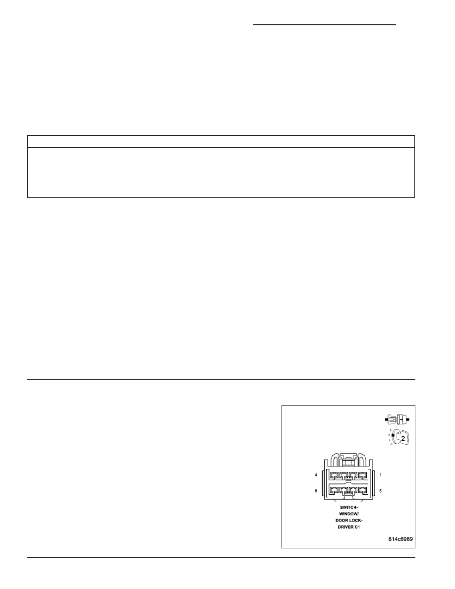
CHECK THE DRIVER WINDOW/DOOR LOCK SWITCH FOR A SHORT TO VOLTAGE
With the scan tool, erase DTCs.
Turn the ignition off.
Disconnect the Driver Window/Door Lock Switch C1 connector.
Cycle the ignition 3 times.
Turn the ignition on.
With the scan tool, read DTCs.
Does the scan tool display: B1D4C MEMORY SWITCH INPUT
CIRCUIT HIGH?
Yes
>> Go To 3
No
>> Replace the Driver Window/Door Lock Switch in accor-
dance with the Service Information.
Perform BODY VERIFICATION TEST – VER 1. (Refer to 8
- ELECTRICAL/ELECTRONIC CONTROL MODULES -
STANDARD PROCEDURE).
8N - 184
POWER MIRRORS - ELECTRICAL DIAGNOSTICS
WK