Jeep Grand Cherokee WK. Manual - part 485


  Index      Jeep     Jeep Grand Cherokee WK - service repair manual 2005 year


Search            


Content   ..  483  484  485  486   ..


Jeep Grand Cherokee WK. Manual - part 485


B1D0D, B1D16–MIRROR VERTICAL POSITION SENSOR INPUT CIRCUIT HIGH – MEMORY MIRROR
MODULE (CONTINUED)

2.

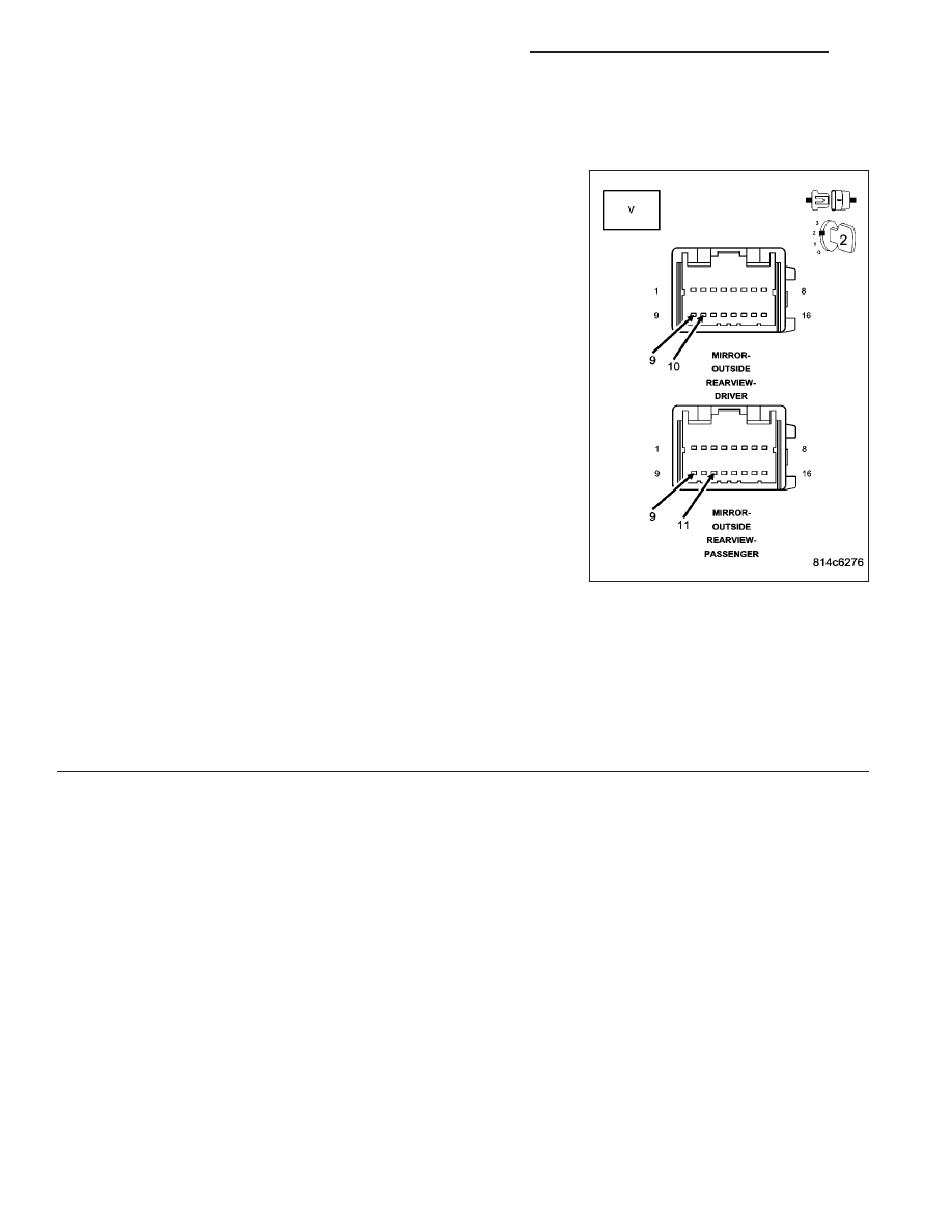
TEST FOR A SHORTED OUTSIDE REARVIEW MIRROR

For the Driver Memory Mirror System, proceed as follows:

Turn the ignition off.

Disconnect the Driver Outside Rearview Mirror connector.

Connect a voltmeter between the (P67) Driver Mirror Vertical
Position Signal circuit and the (P69) Driver Mirror Sensor Ground
circuit.

Turn the ignition on.

Move the mirror switch to any switch position while monitoring
the voltmeter.

For the Passenger Memory Mirror System, proceed as follows:

Turn the ignition off.

Disconnect the Passenger Outside Rearview Mirror connector.

Connect a voltmeter between the (P64) Passenger Mirror Vertical
Position Signal circuit and the (P66) Passenger Mirror Sensor
Ground circuit

Turn the ignition on.

Move the mirror switch to any switch position while monitoring
the voltmeter.

What is the voltage?

4.8 to 5.2 Volts

Replace the Outside Rearview Mirror in accordance with
the Service Information.

Perform BODY VERIFICATION TEST – VER 1. (Refer to 8 - ELECTRICAL/ELECTRONIC CONTROL
MODULES - STANDARD PROCEDURE).

Above 5.2 Volts

Go To 3

Below 4.8 Volts

Go To 4

8N - 100

POWER MIRRORS - ELECTRICAL DIAGNOSTICS

WK

B1D0D, B1D16–MIRROR VERTICAL POSITION SENSOR INPUT CIRCUIT HIGH – MEMORY MIRROR
MODULE (CONTINUED)

3.

CHECK THE (P67) DRIVER MIRROR VERTICAL POSITION SIGNAL CIRCUIT OR THE (P64) PASSENGER
MIRROR VERTICAL POSITION SIGNAL CIRCUIT FOR A SHORT TO VOLTAGE

For the Driver Memory Mirror System, proceed as follows:

Turn the ignition off.

Disconnect the Driver Memory Mirror Module C1 connector.

Turn the ignition on.

Measure the voltage of the (P67) Driver Mirror Vertical Position
Signal circuit.

For the Passenger Memory Mirror System, proceed as follows:

Turn the ignition off.

Disconnect the Passenger Memory Mirror Module connector.

Turn the ignition on.

Measure the voltage of the (P64) Passenger Mirror Vertical Posi-
tion Signal circuit.

Is the voltage above 0.2 volts?

Yes, Driver MMM

Repair the (P67) Driver Mirror Vertical Position Signal cir-
cuit for a short to voltage.

Perform BODY VERIFICATION TEST – VER 1. (Refer to 8
- ELECTRICAL/ELECTRONIC CONTROL MODULES -
STANDARD PROCEDURE).

Yes, Passenger MMM

Repair the (P64) Passenger Mirror Vertical Position Signal
circuit for a short to voltage.

Perform BODY VERIFICATION TEST – VER 1. (Refer to 8
- ELECTRICAL/ELECTRONIC CONTROL MODULES - STANDARD PROCEDURE).

No, Driver MMM

Replace the Driver Memory Mirror Module in accordance with the Service Information.

Perform BODY VERIFICATION TEST – VER 1. (Refer to 8 - ELECTRICAL/ELECTRONIC CONTROL
MODULES - STANDARD PROCEDURE).

No, Passenger MMM

Replace the Passenger Memory Mirror Module in accordance with the Service Information.

Perform BODY VERIFICATION TEST – VER 1. (Refer to 8 - ELECTRICAL/ELECTRONIC CONTROL
MODULES - STANDARD PROCEDURE).

WK

POWER MIRRORS - ELECTRICAL DIAGNOSTICS

8N - 101

B1D0D, B1D16–MIRROR VERTICAL POSITION SENSOR INPUT CIRCUIT HIGH – MEMORY MIRROR
MODULE (CONTINUED)

4.

CHECK THE (P67) DRIVER MIRROR VERTICAL POSITION SIGNAL CIRCUIT OR THE (P64) PASSENGER
MIRROR VERTICAL POSITION SIGNAL CIRCUIT FOR AN OPEN

For the Driver Memory Mirror System, proceed as follows:

Turn the ignition off.

Disconnect the Driver Memory Mirror Module C1 connector.

Measure the resistance of the (P67) Driver Mirror Vertical Posi-
tion Signal circuit between the Driver Outside Rearview Mirror
connector and the Driver Memory Mirror Module C1 connector.

For the Passenger Memory Mirror System, proceed as follows:

Turn the ignition off.

Disconnect the Passenger Memory Mirror Module connector.

Measure the resistance of the (P64) Passenger Mirror Vertical
Position Signal circuit between the Passenger Outside Rearview
Mirror connector and the Passenger Memory Mirror Module con-
nector.

Is the resistance below 2.0 ohms?

Yes

>> Go To 5

No, Driver MMM

Repair the (P67) Driver Mirror Vertical Position Signal cir-
cuit for an open.

Perform BODY VERIFICATION TEST – VER 1. (Refer to 8
- ELECTRICAL/ELECTRONIC CONTROL MODULES -
STANDARD PROCEDURE).

No, Passenger MMM

Repair the (P64) Passenger Mirror Vertical Position Signal
circuit for an open.

Perform BODY VERIFICATION TEST – VER 1. (Refer to 8 - ELECTRICAL/ELECTRONIC CONTROL
MODULES - STANDARD PROCEDURE).

8N - 102

POWER MIRRORS - ELECTRICAL DIAGNOSTICS

WK

B1D0D, B1D16–MIRROR VERTICAL POSITION SENSOR INPUT CIRCUIT HIGH – MEMORY MIRROR
MODULE (CONTINUED)

5.

CHECK THE (P69) DRIVER MIRROR SENSOR GROUND CIRCUIT OR (P66) PASSENGER MIRROR
SENSOR GROUND CIRCUIT FOR AN OPEN

For the Driver Memory Mirror System, proceed as follows:

Measure the resistance of the (P69) Driver Mirror Sensor Ground
circuit between the Driver Outside Rearview Mirror connector and
the Driver Memory Mirror Module C1 connector.

For the Passenger Memory Mirror System, proceed as follows:

Measure the resistance of the (P66) Passenger Mirror Sensor
Ground circuit between the Passenger Outside Rearview Mirror
connector and the Passenger Memory Mirror Module connector.

Is the resistance below 2.0 ohms?

Yes, Driver MMM

Replace the Driver Memory Mirror Module in accordance
with the Service Information.

Perform BODY VERIFICATION TEST – VER 1. (Refer to 8
- ELECTRICAL/ELECTRONIC CONTROL MODULES -
STANDARD PROCEDURE).

Yes, Passenger MMM

Replace the Passenger Memory Mirror Module in accor-
dance with the Service Information.

Perform BODY VERIFICATION TEST – VER 1. (Refer to 8
- ELECTRICAL/ELECTRONIC CONTROL MODULES -
STANDARD PROCEDURE).

No, Driver MMM

Repair the (P69) Driver Mirror Sensor Ground circuit for an
open.

Perform BODY VERIFICATION TEST – VER 1. (Refer to 8 - ELECTRICAL/ELECTRONIC CONTROL
MODULES - STANDARD PROCEDURE).

No, Passenger MMM

Repair the (P66) Passenger Mirror Sensor Ground circuit for an open.

Perform BODY VERIFICATION TEST – VER 1. (Refer to 8 - ELECTRICAL/ELECTRONIC CONTROL
MODULES - STANDARD PROCEDURE).

WK

POWER MIRRORS - ELECTRICAL DIAGNOSTICS

8N - 103


Content   ..  483  484  485  486   ..