Jeep Grand Cherokee WK. Manual - part 482
B1D0A, B1D13–MIRROR POSITION SENSOR POWER SUPPLY CIRCUIT HIGH – MEMORY MIRROR
MODULE (CONTINUED)
3.
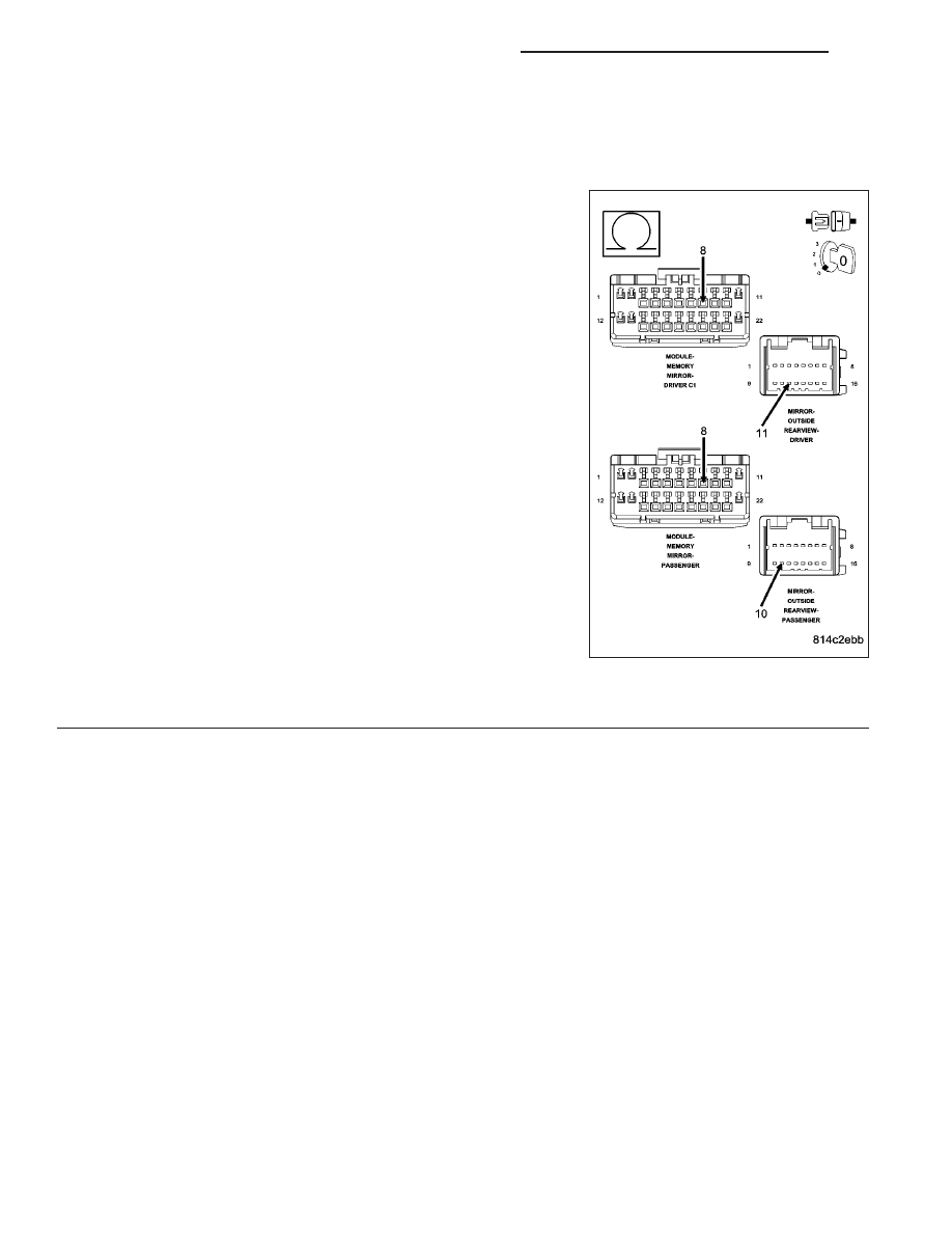
CHECK THE (P669) DRIVER MIRROR SENSOR SUPPLY CIRCUIT OR THE (P666) PASSENGER MIRROR
SENSOR SUPPLY CIRCUIT FOR AN OPEN
For the Driver Memory Mirror System, proceed as follows:
•
Turn the ignition off.
•
Disconnect the Driver Memory Mirror Module C1 connector.
•
Measure the resistance of the (P669) Driver Mirror Sensor Sup-
ply circuit between the Driver Outside Rearview Mirror connector
and the Driver Memory Mirror Module C1 connector.
For the Passenger Memory Mirror System, proceed as follows:
•
Turn the ignition off.
•
Disconnect the Passenger Memory Mirror Module connector.
•
Measure the resistance of the (P666) Passenger Mirror Sensor
Supply circuit between the Passenger Outside Rearview Mirror
connector and the Passenger Memory Mirror Module connector.
Is the resistance below 2.0 ohms?
Yes
>> Go To 4
No, Driver MMM
Repair the (P669) Driver Mirror Sensor Supply circuit for
an open.
Perform BODY VERIFICATION TEST – VER 1. (Refer to 8
- ELECTRICAL/ELECTRONIC CONTROL MODULES -
STANDARD PROCEDURE).
No, Passenger MMM
Repair the (P666) Passenger Mirror Sensor Supply circuit
for an open.
Perform BODY VERIFICATION TEST – VER 1. (Refer to 8 - ELECTRICAL/ELECTRONIC CONTROL
MODULES - STANDARD PROCEDURE).
8N - 88
POWER MIRRORS - ELECTRICAL DIAGNOSTICS
WK