Jeep Grand Cherokee WK. Manual - part 417
 

  Index      Jeep     Jeep Grand Cherokee WK - service repair manual 2005 year


Search            


Content   ..  415  416  417  418   ..


Jeep Grand Cherokee WK. Manual - part 417


B2123-IGNITION RUN CONTROL CIRCUIT HIGH (CONTINUED)

3.

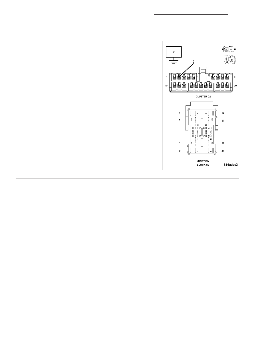
(F102) IGNITION RUN RELAY CONTROL CIRCUIT SHORTED TO BATTERY

Disconnect the Junction Block C2 connector (on top of junction block).

Measure the voltage between ground and the (F102) Ignition Run
Relay Control circuit in the Cluster C2 connector.

Turn the ignition on.

Is there any voltage present?

Yes

>> Repair the (F102) Ignition Run Relay Control circuit for a

short to voltage.

Perform BODY VERIFICATION TEST - VER 1. (Refer to 8
- ELECTRICAL/ELECTRONIC CONTROL MODULES -
STANDARD PROCEDURE)

No

>> Replace the Junction Block in accordance with service

information.

Perform BODY VERIFICATION TEST - VER 1. (Refer to 8
- ELECTRICAL/ELECTRONIC CONTROL MODULES -
STANDARD PROCEDURE)

8J - 42

INSTRUMENT CLUSTER - ELECTRICAL DIAGNOSTICS

WK

B2213–CCN INTERNAL

For a complete wiring diagram Refer to Section 8W.

When Monitored:
With the Instrument Cluster awake.

Set Condition:
The Instrument Cluster detects an internal failure.

Possible Causes

INSTRUMENT CLUSTER

Diagnostic Test

1.

REPLACE THE INSTRUMENT CLUSTER

When this code is set, the Instrument Cluster must be replaced.

View Repair

Repair

Replace the Instrument Cluster in accordance with the Service Information.

Perform BODY VERIFICATION TEST VER 1. (Refer to 8 - ELECTRICAL/ELECTRONIC CONTROL
MODULES - STANDARD PROCEDURE)

WK

INSTRUMENT CLUSTER - ELECTRICAL DIAGNOSTICS

8J - 43

U0019–CAN B BUS

8J - 44

INSTRUMENT CLUSTER - ELECTRICAL DIAGNOSTICS

WK

U0019–CAN B BUS (CONTINUED)

For a complete wiring diagram Refer to Section 8W.

When Monitored:
With the Instrument Cluster awake.

Set Condition:
Whenever the Can B Bus (+) or B Bus (–) circuit is open, shorted to voltage or shorted to ground, this code
will set.

Possible Causes

CAN B BUS DTCs IN FRONT CONTROL MODULE

(D54) CAN B BUS (–) CIRCUIT OPEN

(D55) CAN B BUS (+) CIRCUIT OPEN

INSTRUMENT CLUSTER

Diagnostic Test

1.

CHECK FOR AN ACTIVE DTC

Turn the ignition on.

With the scan tool, record and erase DTCs.

Cycle the ignition from on to off 3 times.

Turn the ignition on.

With the scan tool, read DTCs.

Is the DTC active?

Yes

>> Go To 2

No

>> The condition that caused this code to set is not present at this time. Check for an intermittent condition

by inspecting the related wiring harness for chaffed, pierced, pinched, and partially broken wires. Also
inspect the related connectors for broken, bent, pushed out, spread, corroded, or contaminated termi-
nals.

Perform BODY VERIFICATION TEST VER 1. (Refer to 8 - ELECTRICAL/ELECTRONIC CONTROL
MODULES - STANDARD PROCEDURE)

2.

CHECK FRONT CONTROL MODULE DTCs

With the scan tool, read Front Control Module DTCs.

Does the scan tool display the U0019–CAN B BUS DTC?

Yes

>> Refer to the symptom list for problems related to Communication in the ELECTRICAL.– ELECTRONIC

CONTROL MODULES – ELECTRICAL DIAGNOSES section.

No

>> Go to 3

WK

INSTRUMENT CLUSTER - ELECTRICAL DIAGNOSTICS

8J - 45


Content   ..  415  416  417  418   ..