Jeep Grand Cherokee WK. Manual - part 416
B2122-IGNITION RUN CONTROL CIRCUIT LOW (CONTINUED)
For the Power Door Lock circuit diagram (Refer to 8 - ELECTRICAL/POWER LOCKS - SCHEMATICS AND DIA-
GRAMS)
For a complete wiring diagram Refer to Section 8W.
•
When Monitored:
Continuously
•
Set Condition:
When the Cluster senses a low condition on the (F102) Ignition Run Relay Control circuit for over 10 seconds,
this code will set.
Possible Causes
(F102) IGNITION RUN RELAY CONTROL CIRCUIT LOW
JUNCTION BLOCK
INSTRUMENT CLUSTER
Diagnostic Test
1.
TEST FOR INTERMITTENT CONDITION
With the scan tool, record and erase DTC’s
Operate the door locks several times.
Cycle the ignition from on to off.
Turn the ignition on.
With the scan tool, read DTC’s.
Does the scan tool display B2122-IGNITION RUN CONTROL CIRCUIT LOW?
Yes
>> Go To 2
No
>> The conditions that caused this code to set are not present at this time. Using the wiring diagram/sche-
matic as a guide, inspect the wiring and connectors.
Perform BODY VERIFICATION TEST - VER 1. (Refer to 8 - ELECTRICAL/ELECTRONIC CONTROL
MODULES - STANDARD PROCEDURE)
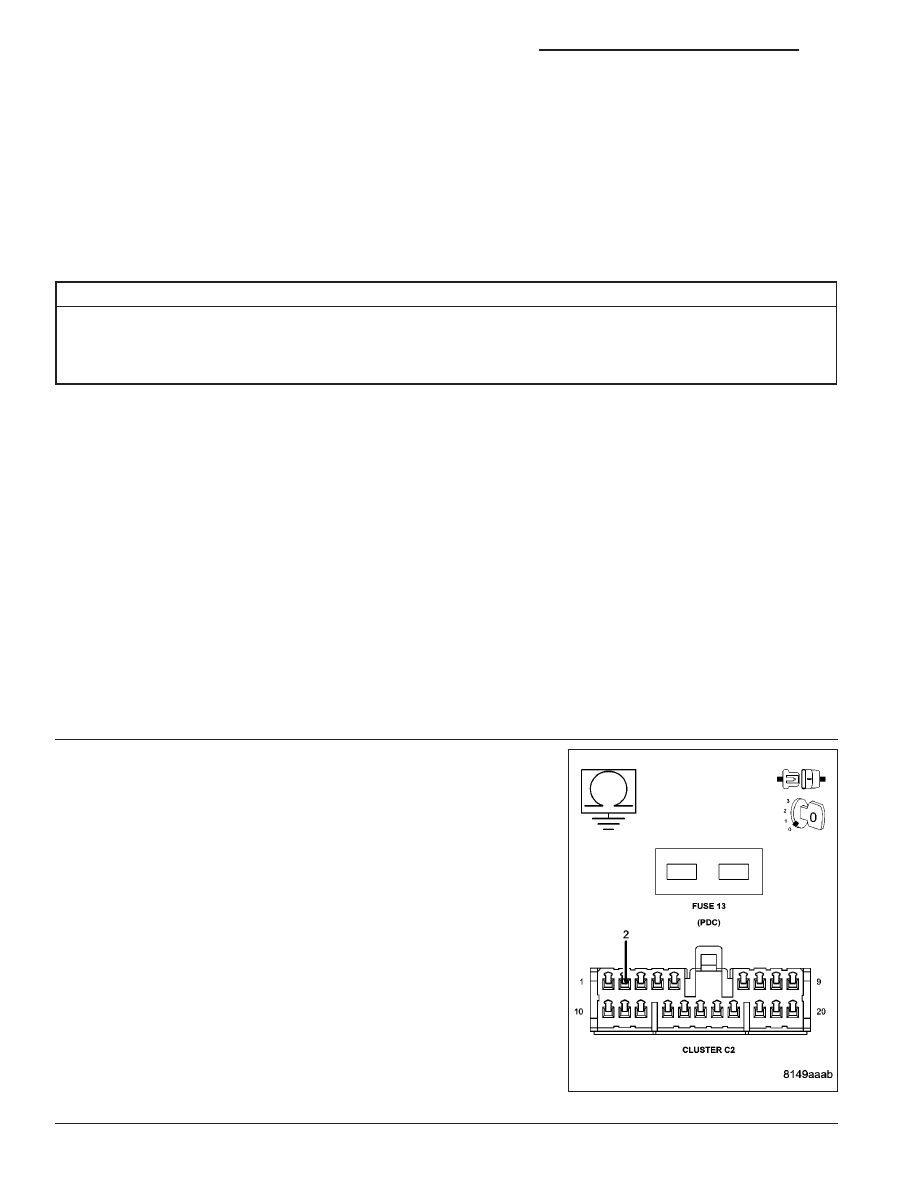
2.
IGNITION RUN RELAY SHORTED
Turn the ignition off.
Disconnect the Cluster C2 connector.
Remove the PDC fuse #13.
Measure the resistance between ground and the (F102) Ignition Run
Relay Control circuit in the Cluster C2 connector
Is the resistance below 1000.0 ohms?
No
>> Replace the Instrument Cluster in accordance with service
information.
Perform BODY VERIFICATION TEST - VER 1. (Refer to 8
- ELECTRICAL/ELECTRONIC CONTROL MODULES -
STANDARD PROCEDURE)
Yes
>> Go To 3
8J - 38
INSTRUMENT CLUSTER - ELECTRICAL DIAGNOSTICS
WK