Jeep Grand Cherokee WK. Manual - part 369
24. Reconnect the battery positive cable terminal
clamp (4) to the battery positive terminal post.
Tighten the terminal clamp pinch-bolt hex nut to
5.6 N·m (50 in. lbs.).
25. Secure the battery positive cable terminal clamp
cover (3) over the battery positive cable terminal
clamp (4).
26. Reconnect the battery negative cable terminal
clamp (2) to the battery negative terminal post.
Tighten the terminal clamp pinch-bolt hex nut to
5.6 N·m (50 in. lbs.).
27. Apply a thin coating of petroleum jelly or chassis
grease to the exposed surfaces of the battery
cable terminal clamps and the battery terminal
posts.
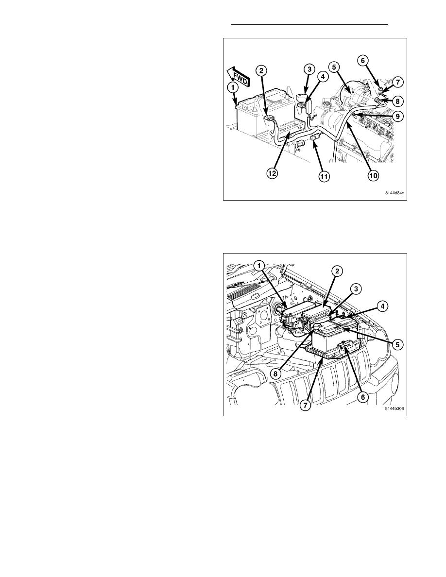
BATTERY TRAY
DESCRIPTION
The battery (5) is mounted in a molded plastic battery
tray and support unit (7) located in the left front corner
of the engine compartment. The battery tray and sup-
port unit is secured at the rear with a nut to a stud on
the front frame rail, at the outboard side with two
screws fastened to the left side inner fender panel,
and at the front with a screw on a bracket off the radi-
ator support.
8F - 28
BATTERY SYSTEM - SERVICE INFORMATION
WK