Jeep Grand Cherokee WK. Manual - part 348
*NO RESPONSE FROM TCM - NAG1/DIESEL (CONTINUED)
5.
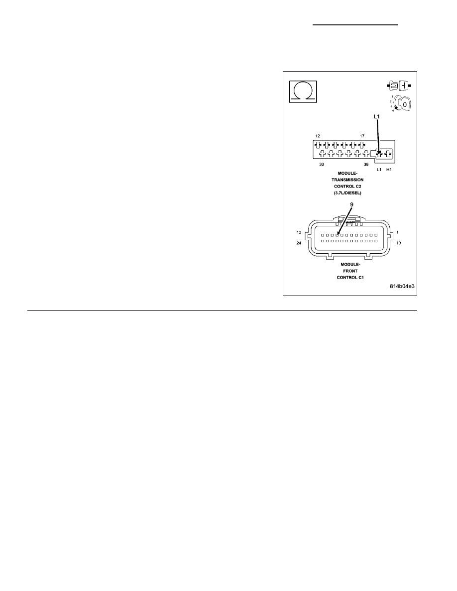
(D64) CAN C BUS (-) CIRCUIT OPEN
Measure the resistance of the (D64) CAN C Bus (-) circuit between
the FCM connector and the TCM connector.
Is resistance below 5.0 ohms?
Yes
>> Replace the Transmission Control Module in accordance
with the service information.
Perform NAG1/Diesel TRANSMISSION VERIFICATION
TEST - VER 1.
No
>> Repair the (D64) CAN C Bus (-) circuit for an open.
Perform NAG1/Diesel TRANSMISSION VERIFICATION
TEST - VER 1.
8E - 238
ELECTRONIC CONTROL MODULES - ELECTRICAL DIAGNOSTICS
WK