Jeep Grand Cherokee WK. Manual - part 257


  Index      Jeep     Jeep Grand Cherokee WK - service repair manual 2005 year


Search            


Content   ..  255  256  257  258   ..


Jeep Grand Cherokee WK. Manual - part 257


AMPLIFIER

DESCRIPTION

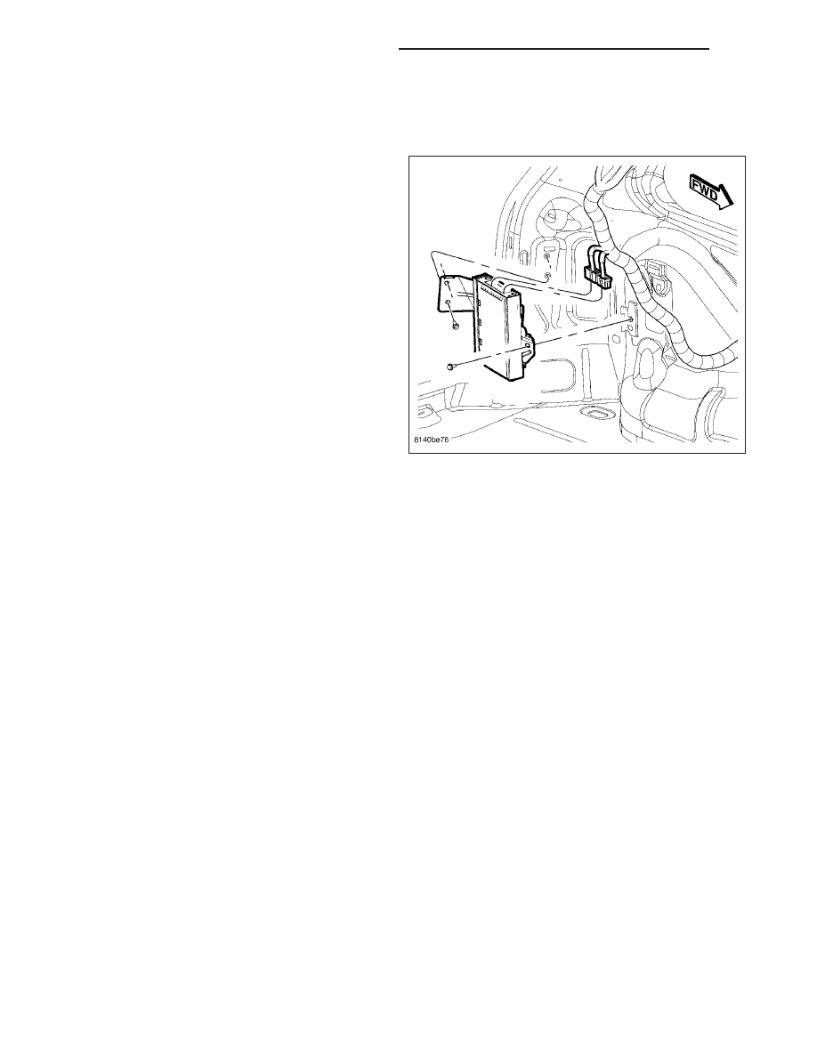
Vehicles equipped with the Boston Acoustics speaker
package have a separate amplifier unit. The amplifier
(2) is rated at 288 watts. The amplifier is mounted to
the left rear quarter panel behind the quarter trim
panel.

OPERATION

The amplifier receives fused battery current from a fuse in the Integrated Power Module (IPM) at all times. The
internal circuitry of the amplifier switches the amplifier on based upon a CAN bus message that is received from the
radio receiver whenever the radio is turned on. The amplifier receives the sound signal inputs from the left and right
rear outputs of the radio, then sends the amplified speaker outputs for each of those channels to the speakers.

DIAGNOSIS AND TESTING

AMPLIFIER

Any diagnosis of the Audio system should begin with the use of a scan tool and the appropriate Diagnostic
Service information.

For complete circuit diagrams, refer to the appropriate wiring information.

The amplifier unit should be checked if there is no sound output noted from the speakers. For diagnosis of the
power amplifier, (Refer to 8 - ELECTRICAL/AUDIO/SPEAKER - DIAGNOSIS AND TESTING).

8A - 164

AUDIO/VIDEO - SERVICE INFORMATION

WK

REMOVAL

WARNING: ON VEHICLES EQUIPPED WITH AIR-
BAGS,

DISABLE

THE

SUPPLEMENTAL

RESTRAINT SYSTEM BEFORE ATTEMPTING ANY
STEERING WHEEL, STEERING COLUMN, DRIVER
AIRBAG, PASSENGER AIRBAG, SEAT BELT TEN-
SIONER, SIDE CURTAIN AIRBAG, FRONT IMPACT
SENSOR, SIDE IMPACT SENSOR, OR INSTRU-
MENT PANEL COMPONENT DIAGNOSIS OR SER-
VICE. DISCONNECT AND ISOLATE THE BATTERY
NEGATIVE (GROUND) CABLE, THEN WAIT TWO
MINUTES FOR THE SYSTEM CAPACITOR TO DIS-
CHARGE BEFORE PERFORMING FURTHER DIAG-
NOSIS OR SERVICE. THIS IS THE ONLY SURE
WAY

TO

DISABLE

THE

SUPPLEMENTAL

RESTRAINT SYSTEM. FAILURE TO TAKE THE
PROPER PRECAUTIONS COULD RESULT IN ACCI-
DENTAL AIRBAG DEPLOYMENT AND POSSIBLE
PERSONAL INJURY.

1. Disconnect and isolate the battery negative cable.

2. Remove the left quarter trim panel.

3. Disconnect the two wire harness connectors from

the amplifier.

4. Remove the mounting fasteners.

5. Remove the amplifier.

INSTALLATION

WARNING: ON VEHICLES EQUIPPED WITH AIR-
BAGS,

DISABLE

THE

SUPPLEMENTAL

RESTRAINT SYSTEM BEFORE ATTEMPTING ANY
STEERING WHEEL, STEERING COLUMN, DRIVER
AIRBAG, PASSENGER AIRBAG, SEAT BELT TEN-
SIONER, SIDE CURTAIN AIRBAG, FRONT IMPACT
SENSOR, SIDE IMPACT SENSOR, OR INSTRU-
MENT PANEL COMPONENT DIAGNOSIS OR SER-
VICE. DISCONNECT AND ISOLATE THE BATTERY
NEGATIVE (GROUND) CABLE, THEN WAIT TWO
MINUTES FOR THE SYSTEM CAPACITOR TO DIS-
CHARGE BEFORE PERFORMING FURTHER DIAG-
NOSIS OR SERVICE. THIS IS THE ONLY SURE
WAY

TO

DISABLE

THE

SUPPLEMENTAL

RESTRAINT SYSTEM. FAILURE TO TAKE THE
PROPER PRECAUTIONS COULD RESULT IN ACCI-
DENTAL AIRBAG DEPLOYMENT AND POSSIBLE
PERSONAL INJURY.

1. Position the amplifier into place.

2. Install and tighten the mounting fasteners.

3. Connect the two wire harness connectors.

4. Install the left quarter trim panel.

5. Connect the battery negative cable.

WK

AUDIO/VIDEO - SERVICE INFORMATION

8A - 165

ANTENNA BODY & CABLE

DESCRIPTION

DOMESTIC

The antenna body and cable is secured below the
fender panel by the antenna cap nut through a mount-
ing hole in the side of the right front fender. The pri-
mary coaxial antenna cable is then routed beneath the
fender sheet metal and through a entry hole in the
right cowl side panel into the interior of the vehicle.
Inside the vehicle, the primary coaxial cable is con-
nected to a secondary instrument panel antenna coax-
ial cable with an in-line connector that is located
behind the right kick panel. The instrument panel
antenna cable is then routed behind the instrument
panel to the back of the radio.

EXPORT

The primary coaxial antenna cable (1) is routed behind the A-pillar trim, up the right side of the roof panel above the
headliner. The cable is connected to a secondary instrument panel antenna coaxial cable with an in-line connector
that is located behind the A-pillar trim. At the other end, the cable is connected to the antenna module (2). The
instrument panel antenna cable is then routed behind the instrument panel to the back of the radio.

8A - 166

AUDIO/VIDEO - SERVICE INFORMATION

WK

OPERATION

The antenna body and cable connects the antenna mast to the radio. The radio antenna is an electromagnetic
circuit component used to capture radio frequency signals that are broadcast by local commercial radio stations in
both the Amplitude Modulating (AM) and Frequency Modulating (FM) frequency ranges. These electromagnetic radio
frequency signals induce small electrical modulations into the antenna as they move past the mast. The antenna
body transfers the weak electromagnetic radio waves induced into the rigid antenna mast into the center conductor
of the flexible primary antenna coaxial cable. The braided outer shield of the antenna coaxial cable is grounded
through both the antenna body and the radio chassis, effectively shielding the radio waves as they are conducted to
the radio. The radio then tunes and amplifies the weak radio signals into stronger electrical signals in order to oper-
ate the audio system speakers.

DIAGNOSIS AND TESTING

ANTENNA BODY AND CABLE

The following four tests are used to diagnose the
antenna with an ohmmeter:

Test 1 - Mast to ground test

Test 2 - Tip-of-mast to tip-of-conductor test

Test 3 - Body ground to battery ground
test

Test 4 - Body ground to antenna
coaxial cable shield test.

WARNING: ON VEHICLES EQUIPPED WITH AIR-
BAGS, DISABLE THE AIRBAG SYSTEM BEFORE
ATTEMPTING ANY STEERING WHEEL, STEERING
COLUMN, OR INSTRUMENT PANEL COMPONENT
DIAGNOSIS OR SERVICE. DISCONNECT AND ISO-
LATE

THE

BATTERY

NEGATIVE

(GROUND)

CABLE, THEN WAIT TWO MINUTES FOR THE AIR-
BAG

SYSTEM

CAPACITOR

TO

DISCHARGE

BEFORE PERFORMING FURTHER DIAGNOSIS OR
SERVICE. THIS IS THE ONLY SURE WAY TO DIS-
ABLE THE AIRBAG SYSTEM. FAILURE TO TAKE
THE PROPER PRECAUTIONS COULD RESULT IN
ACCIDENTAL AIRBAG DEPLOYMENT AND POSSI-
BLE PERSONAL INJURY.

The ohmmeter test lead connections for each test are
shown in the illustration.

NOTE: This model has a two-piece antenna coaxial cable. Tests 2 and 4 must be conducted in two steps to
isolate an antenna cable problem. First, test the primary antenna cable (integral to the antenna body and
cable) from the coaxial cable connector under the right end of the instrument panel near the right cowl side
inner panel to the antenna body. Then, test the secondary antenna cable (instrument panel antenna cable)
from the coaxial cable connector under the right end of the instrument panel near the right cowl side inner
panel to the coaxial cable connector at the radio.

NOTE: Use extreme caution when checking continuity of center conductor to avoid damage.

TEST 1

Test 1 determines if the antenna mast is insulated from ground. Proceed as follows:

1. Disconnect and isolate the antenna coaxial cable connector under the right end of the instrument panel near the

right cowl side inner panel.

WK

AUDIO/VIDEO - SERVICE INFORMATION

8A - 167


Content   ..  255  256  257  258   ..