Index Jeep Jeep Grand Cherokee WK - service repair manual 2005 year
Search
Content .. 253 254 255 256 ..
Jeep Grand Cherokee WK. Manual - part 255
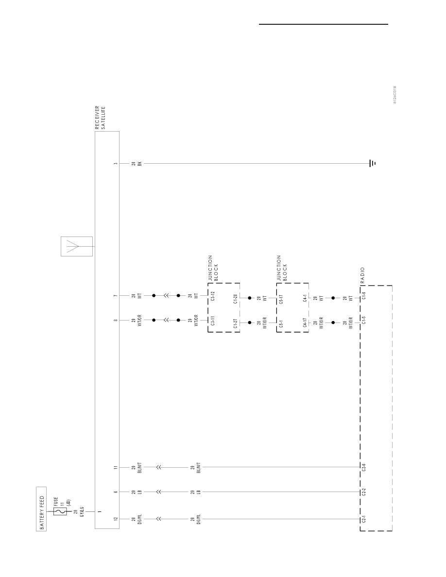
SA
TELLITE
RADIO
8A - 156
AUDIO/VIDEO SYSTEMS - ELECTRICAL DIAGNOSIS
WK