Jeep Grand Cherokee WK. Manual - part 184
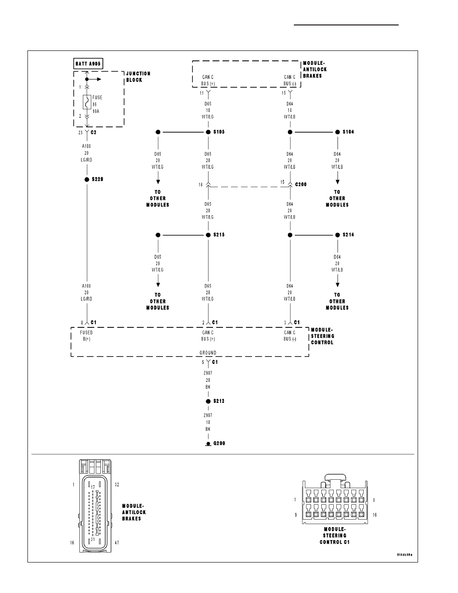
C2205-STEERING ANGLE SENSOR INTERNAL
5 - 362
BRAKES - BRAKE CONTROLLER ELECTRICAL DIAGNOSTICS
WK
|
|
|
C2205-STEERING ANGLE SENSOR INTERNAL 5 - 362 BRAKES - BRAKE CONTROLLER ELECTRICAL DIAGNOSTICS WK |