Jeep Grand Cherokee WK. Manual - part 1783


  Index      Jeep     Jeep Grand Cherokee WK - service repair manual 2005 year


Search            


Content   ..  1781  1782  1783  1784   ..


Jeep Grand Cherokee WK. Manual - part 1783


8. Disconnect the A/C discharge line from the A/C condenser and remove and discard the dual plane seal.

9. Install plugs in, or tape over the opened discharge line fittings and the compressor and condenser ports.

10. Remove the A/C discharge line from the engine compartment.

5.7L ENGINE

WARNING: Refer to the applicable warnings and cautions for this system before performing the following
operation (Refer to 24 - HEATING & AIR CONDITIONING/PLUMBING - WARNINGS) and (Refer to 24 - HEAT-
ING & AIR CONDITIONING/PLUMBING - CAUTIONS). Failure to follow the warnings and cautions could result
in possible personal injury or death.

1. Recover the refrigerant from the refrigerant system

(Refer to 24 - HEATING & AIR CONDITIONING/
PLUMBING

-

STANDARD

PROCEDURE

-

REFRIGERANT SYSTEM RECOVERY).

2. Disconnect and isolate the negative battery cable.

3. Remove the grille (Refer to 23 - BODY/EXTERIOR/

GRILLE - REMOVAL).

4. Remove the air cleaner housing, air intake tube

and the resonator (Refer to 9 - ENGINE/AIR
INTAKE

SYSTEM/HOUSING-AIR

CLEANER

-

REMOVAL).

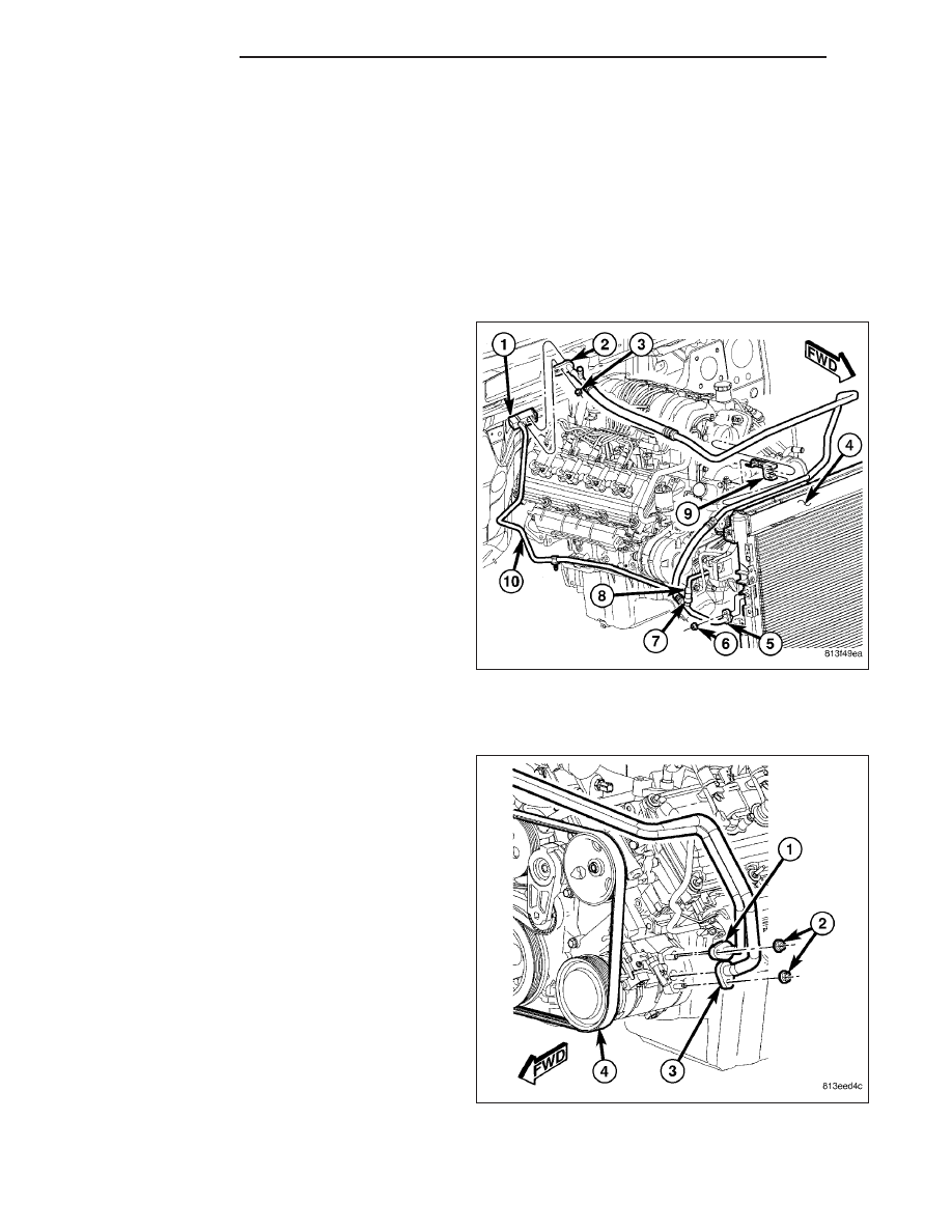
5. Disconnect the wire harness connector (8) from the

A/C pressure transducer (7) and remove the trans-
ducer from the A/C discharge line (5), if required.

6. Remove the nut (6) that secures the A/C discharge

line to the A/C condenser (4).

7. Disconnect the A/C discharge line from the A/C

condenser and the retaining bracket (9) and
remove and discard the dual plane seal.

8. Remove the nut (2) that secures the A/C discharge

line (1) to the A/C compressor (4).

9. Disconnect the A/C discharge line from the A/C

compressor and remove and discard the dual plane
seal.

10. Install plugs in, or tape over the opened refriger-

ant line fittings and the compressor and con-
denser ports.

11. Remove the A/C discharge line from the engine

compartment.

24 - 480

PLUMBING

WK

INSTALLATION

3.7L/4.7L ENGINES

1. Position the A/C discharge line (4) into the engine

compartment.

2. Remove the tape or plugs from the discharge line

fittings and the A/C compressor (2) and A/C con-
denser (3).

3. Lubricate new dual plane seals with clean refriger-

ant oil and install them onto the A/C discharge line.
Use only the specified seals as they are made of a
special material for the R-134a system. Use only
refrigerant oil of the type recommended for the A/C
compressor in the vehicle.

4. Install the A/C discharge line onto the A/C com-

pressor.

5. Install the nut (1) that secures the A/C discharge

line to the A/C compressor. Tighten the nut to 20
N·m (15 ft. lbs.).

6. Install the A/C discharge line onto the A/C con-

denser.

7. Install the nut (5) that secures the A/C discharge line to the A/C condenser. Tighten the nut to 20 N·m (15 ft.

lbs.).

8. Install the air cleaner housing, air intake tube and the resonator (Refer to 9 - ENGINE/AIR INTAKE SYSTEM/AIR

CLEANER HOUSING - INSTALLATION).

9. Install the grille (Refer to 23 - BODY/EXTERIOR/GRILLE - INSTALLATION).

10. Reconnect the negative battery cable.

11. Evacuate the refrigerant system (Refer to 24 - HEATING & AIR CONDITIONING/PLUMBING - STANDARD

PROCEDURE - REFRIGERANT SYSTEM EVACUATE).

12. Charge the refrigerant system (Refer to 24 - HEATING & AIR CONDITIONING/PLUMBING - STANDARD PRO-

CEDURE - REFRIGERANT SYSTEM CHARGE).

5.7L ENGINE

1. Position the A/C discharge line (1) into the engine

compartment.

2. Remove the tape or plugs from the opened dis-

charge line fittings and the compressor and con-
denser ports.

3. Lubricate new dual plane seals with clean refriger-

ant oil and install them onto the discharge line fit-
tings. Use only the specified seals as they are
made of a special material for the R-134a system.
Use only refrigerant oil of the type recommended
for the A/C compressor in the vehicle.

4. Install the A/C discharge line onto the A/C com-

pressor (4).

5. Install the nut (2) that secures the A/C discharge

line to the A/C compressor. Tighten the nut to 20

WK

PLUMBING

24 - 481

N·m (15 ft. lbs.).

6. Install the A/C discharge line (5) into the retaining

bracket (9) and to the A/C condenser (4).

7. Install the nut (6) that secures the A/C discharge

line to the A/C condenser. Tighten the nut to 20
N·m (15 ft. lbs.).

8. If removed, install the A/C pressure transducer (7)

onto the A/C discharge line. Tighten the A/C pres-
sure transducer securely.

9. Connect the wire harness connector (8) to the A/C

pressure transducer.

10. Install the air cleaner housing, air intake tube and

the resonator (Refer to 9 - ENGINE/AIR INTAKE
SYSTEM/HOUSING-AIR CLEANER - INSTALLA-
TION).

11. Install the grille (Refer to 23 - BODY/EXTERIOR/

GRILLE - INSTALLATION).

12. Reconnect the negative battery cable.

13. Evacuate the refrigerant system (Refer to 24 -

HEATING & AIR CONDITIONING/PLUMBING -
STANDARD

PROCEDURE

-

REFRIGERANT

SYSTEM EVACUATE).

14. Charge the refrigerant system (Refer to 24 - HEATING & AIR CONDITIONING/PLUMBING - STANDARD PRO-

CEDURE - REFRIGERANT SYSTEM CHARGE).

LINE-A/C LIQUID

DESCRIPTION

The A/C liquid line (1) is the refrigerant line that car-
ries refrigerant from the reciever/drier to the A/C
expansion valve (2). The A/C liquid is serviced in one
section and is secured to the right side frame (3) rail
by two plastic retainer clips (4).

CAUTION: Use only seals specified for the vehicle.
Failure to use the correct seals will cause the
refrigerant system connections to leak.

The A/C liquid line has no serviceable parts except for
the O-ring and dual plane seal. The seals used on the
connections are made from a special type of rubber
not affected by R-134a refrigerant. The seals must be
replaced whenever the A/C liquid line is removed and
installed.

If the A/C liquid line is found to be leaking or dam-
aged, it must be replaced.

24 - 482

PLUMBING

WK

REMOVAL

WARNING: Refer to the applicable warnings and cautions for this system before performing the following
operation (Refer to 24 - HEATING & AIR CONDITIONING/PLUMBING - WARNINGS) and (Refer to 24 - HEAT-
ING & AIR CONDITIONING/PLUMBING - CAUTIONS). Failure to follow the warnings and cautions could result
in possible personal injury or death.

1. Recover the refrigerant from the refrigerant system

(Refer to 24 - HEATING & AIR CONDITIONING/
PLUMBING

-

STANDARD

PROCEDURE

-

REFRIGERANT SYSTEM RECOVERY).

2. Disconnect and isolate the negative battery cable.

3. Remove the air cleaner housing, air intake tube

and the resonator (Refer to 9 - ENGINE/AIR
INTAKE

SYSTEM/HOUSING-AIR

CLEANER

-

REMOVAL).

NOTE: 4.7L engine shown in illustration. Vehicles
equipped with other engines are similar.

4. Remove the nut (3) that secures the A/C suction

line (2) and the A/C liquid line (10) to the A/C
expansion valve (1).

5. Disconnect the A/C suction line from the A/C

expansion valve and remove and discard the
O-ring seal.

6. Remove the nut (1) that secures the A/C liquid line

(2) to the receiver/drier (3).

7. Disconnect the A/C liquid line from the receiver/

drier and remove and discard the dual plane seal.

WK

PLUMBING

24 - 483


Content   ..  1781  1782  1783  1784   ..