Jeep Grand Cherokee WK. Manual - part 1776


  Index      Jeep     Jeep Grand Cherokee WK - service repair manual 2005 year


Search            


Content   ..  1774  1775  1776  1777   ..


Jeep Grand Cherokee WK. Manual - part 1776


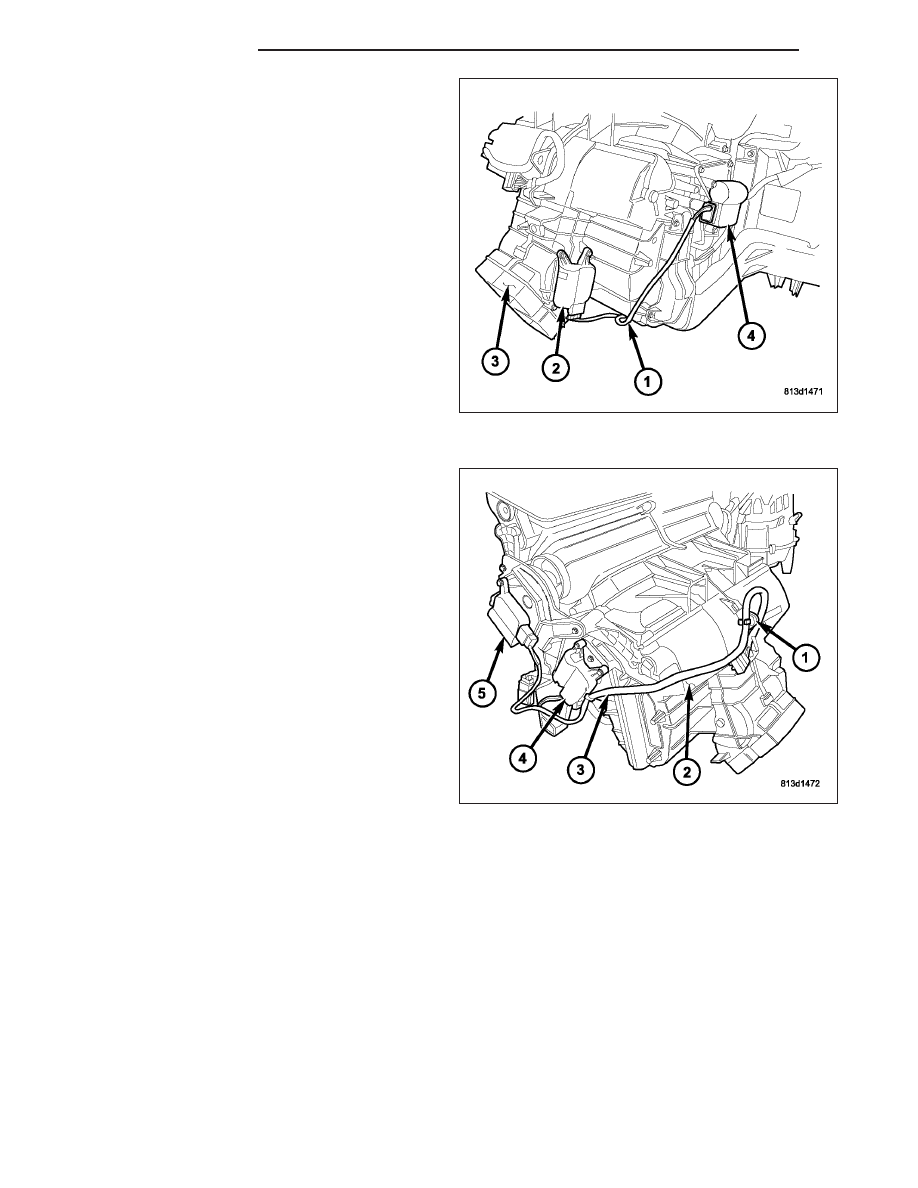
11. Connect the HVAC wire harness (1) to the mode

door actuator (2) located near the bottom of the
air distribution housing (3).

12. If equipped with dual zone heating-A/C, connect

the HVAC wire harness to the blend door actuator
(4) located on the passenger side of the air distri-
bution housing.

13. Connect the HVAC wire harness (3) to the blend

door actuator (4) and the mode door actuator (5)
located on the driver side of the air distribution
housing (2).

14. Engage the HVAC wire harness retainer (1) to the

rear of the air distribution housing.

15. Install the HVAC housing assembly (Refer to 24 -

HEATING & AIR CONDITIONING/DISTRIBUTION/
HOUSING-HVAC - HVAC HOUSING ASSEMBLY -
INSTALLATION).

AIR INLET HOUSING

NOTE: The air inlet housing must be removed from HVAC housing and disassembled for service of the
recirculation-air door.

24 - 452

DISTRIBUTION

WK

1. Position the air distribution housing (4) onto the top

of the HVAC housing (5) by inserting the two tabs
located at the front of the air inlet housing into the
slots located on the top of the HVAC housing.

2. Tip the air distribution housing downward until it is

properly seated on the HVAC housing.

3. Install the three screws (3) that secure the air dis-

tribution housing to the HVAC housing. Tighten the
screws to 2.2 N·m (20 in. lbs.).

4. Connect the HVAC wire harness (1) to the recircu-

lation door actuator (2).

5. Install the HVAC housing assembly (Refer to 24 -

HEATING & AIR CONDITIONING/DISTRIBUTION/
HOUSING-HVAC - HVAC HOUSING ASSEMBLY -
INSTALLATION).

HVAC HOUSING ASSEMBLY

NOTE: The HVAC housing must be removed from the vehicle and disassembled for service of the air inlet
housing, air distribution housing and the A/C evaporator.

1. Position the HVAC housing assembly (2) into the

passenger compartment side of the dash panel (3).
Make sure that the condensate drain tube pro-
trudes through the opening in the floor panel.

2. Loosely install the nut (1) that secures the HVAC

housing to the passenger compartment side of the
dash panel.

WK

DISTRIBUTION

24 - 453

3. Install the two bolts (1) that secure the HVAC hous-

ing assembly (2) to the engine compartment side of
the dash panel (3). Tighten the bolts to 7 N·m (62
in. lbs.).

4. Connect the heater hoses to the heater core tubes.

5. Connect the A/C suction line and A/C liquid line to

the A/C evaporator (Refer to 24 - HEATING & AIR
CONDITIONING/PLUMBING /LINE-A/C LIQUID -
INSTALLATION).

6. Tighten the nut (1) that secures the HVAC housing

assembly (2) to the passenger compartment side of
the dash panel (3) to 7 N·m (62 in. lbs.).

24 - 454

DISTRIBUTION

WK

7. Connect the right front floor duct (5) and left front

floor duct (6) to the air distribution housing (4).

8. Connect the rear floor distribution duct (3) to the air

distribution housing.

9. Connect the left rear floor duct (1) and the right

rear floor duct (2) to the rear floor distribution duct.

10. Position the gear selector (3) to its installed loca-

tion on the floor panel (6) and securely install the
retaining screws (5).

11. Connect the front console duct (2) to the air dis-

tribution housing (4) and engage the push-pin
retainer (1) to the gear selector.

12. Install the instrument panel (Refer to 23 - BODY/

INSTRUMENT

PANEL/INSTRUMENT

PANEL

ASSEMBLY - INSTALLATION).

13. Install the floor console (Refer to 23 - BODY/IN-

TERIOR/FLOOR CONSOLE - INSTALLATION).

14. Reconnect the negative battery cable.

15. If the heater core is being replaced, flush the

cooling system (Refer to 7 - COOLING - STAN-
DARD

PROCEDURE

-

COOLING

SYSTEM

CLEANING/REVERSE FLUSHING).

16. Refill the engine cooling system (Refer to 7 -

COOLING - STANDARD PROCEDURE - COOL-
ING SYSTEM REFILL).

17. Evacuate the refrigerant system (Refer to 24 - HEATING & AIR CONDITIONING/PLUMBING - STANDARD

PROCEDURE - REFRIGERANT SYSTEM EVACUATE).

18. Charge the refrigerant system (Refer to 24 - HEATING & AIR CONDITIONING/PLUMBING - STANDARD PRO-

CEDURE - REFRIGERANT SYSTEM CHARGE).

WK

DISTRIBUTION

24 - 455


Content   ..  1774  1775  1776  1777   ..