Jeep Grand Cherokee WK. Manual - part 1774


  Index      Jeep     Jeep Grand Cherokee WK - service repair manual 2005 year


Search            


Content   ..  1772  1773  1774  1775   ..


Jeep Grand Cherokee WK. Manual - part 1774


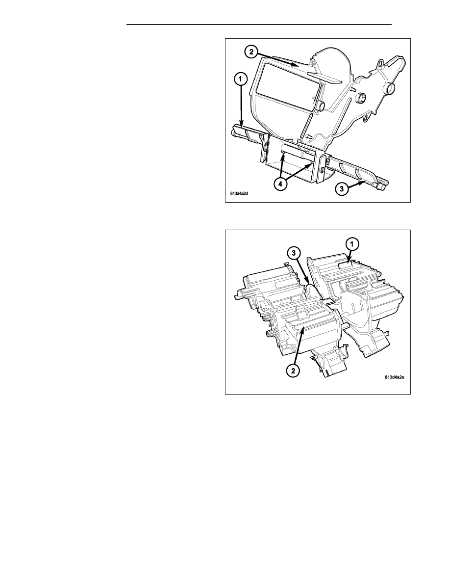
3. If removed, align the front floor-air doors (1 and 3)

with each other and install then into the center par-
tition (2). Make sure that the air door retaining tabs
(4) are fully engaged.

4. Install the center partition (3) into the right half of

the air distribution housing (2).

5. Install the left half of the air distribution housing (1)

onto the right half of the air distribution housing.
Align the air door pivot shafts with each other and
with the pivot shaft holes in the housing.

24 - 444

DISTRIBUTION

WK

6. Install the eight screws (5) that secure the two

halves of the air distribution housing (3) together.
Tighten the screws to 2.2 N·m (20 in. lbs.).

7. Install the four metal clips (4) that secure the two

halves of the air distribution housing together.

8. Inspect the foam seal (1), especially at the parting

line (2). If the seal is deformed or damaged, it must
be replaced.

9. Carefully install the heater core (3) into the passen-

ger side of the air distribution housing (2).

10. If equipped with dual zone heating-A/C, install the

blend door stop (1) onto the passenger side of the
air distribution housing.

WK

DISTRIBUTION

24 - 445

11. Position the rear floor/console door actuator (2)

onto the passenger side of the air distribution
housing (3). If necessary, rotate the actuator
slightly to align the splines on the actuator output
shaft with those on the floor/console door pivot
shaft. (Refer to 24 - HEATING & AIR CONDI-
TIONING/CONTROLS/ACTUATOR-MODE DOOR
- INSTALLATION).

12. Install the screws (1) that secure the rear floor/

console door actuator onto the passenger side of
the air distribution housing. Tighten the screws to
2 N·m (17 in. lbs.).

13. If equipped with dual zone heating-A/C, position

the blend door actuator mounting bracket (5) onto
the passenger side of the air distribution housing
and install the retaining screws (4). Tighten the
screws to 2 N·m (17 in. lbs.).

14. If equipped with dual zone heating-A/C, position

the blend door actuator (7) onto the blend door
actuator mounting bracket and install the retaining
screws (6). Tighten the screws to 2 N·m (17 in.
lbs.). If necessary, rotate the actuator slightly to
align the splines on the actuator output shaft with
those on the blend door stop. (Refer to 24 -
HEATING & AIR CONDITIONING/CONTROLS/
ACTUATOR-BLEND DOOR - INSTALLATION).

15. Install the front floor door linkage rod (6) and the

lower defrost/panel door pivot gear (2) onto the
driver side of the air distribution housing (3).

NOTE: Align the arrow on the lower defrost/panel
door pivot gear with the locator in the window of
the mode door cam during installation of the mode
door cam.

16. Align and install the mode door cam (7) onto the

driver side of the air distribution housing.

NOTE: Align the guide pin on the upper defrost/
panel door linkage rod with the guides in the
mode door cam during installation of the upper
defrost/panel door linkage rod.

17. Align and install the upper defrost/panel door link-

age rod (8) onto the driver side of the air distribu-
tion housing.

NOTE: Align the detent in the upper defrost/panel door pivot gear with the locator in the upper defrost/panel
door linkage rod during installation of the upper defrost/panel door pivot gear.

18. Align and install the blend door stop (5), front floor door pivot gear (4) and the upper defrost/panel door pivot

gear (1) onto the driver side of the air distribution housing.

24 - 446

DISTRIBUTION

WK

19. Position the blend door actuator mounting bracket

(5) and the mode door actuator mounting bracket
(8) onto the driver side of the air distribution hous-
ing (1) and install the retaining screws (3 and 6).
Tighten the screws to 2 N·m (17 in. lbs.).

20. Position the blend door actuator (4) and the mode

door actuator (7) onto the mounting brackets and
install the retaining screws (2). Tighten the screws
to 2 N·m (17 in. lbs.). If necessary, rotate the
actuators slightly to align the splines on the actua-
tor output shaft with those on the mode door cam
and the blend door stop (Refer to 24 - HEATING
& AIR CONDITIONING/CONTROLS/ACTUATOR-
BLEND DOOR - INSTALLATION) and (Refer to
24 - HEATING & AIR CONDITIONING/CON-
TROLS/ACTUATOR-MODE DOOR - INSTALLA-
TION).

21. Install the air distribution housing onto the HVAC

housing (Refer to 24 - HEATING & AIR CONDI-
TIONING/DISTRIBUTION/HOUSING-HVAC - AIR
DISTRIBUTION HOUSING - INSTALLATION).

AIR INLET HOUSING

NOTE: The air inlet housing must be removed from HVAC housing and disassembled for service of the
recirculation-air door.

1. Position the recirculation-air door (4) into the air

inlet housing (1).

CAUTION: Make sure that the recirculation-air
door pivot shaft is properly seated in the pivot
seats located on the air inlet housing.

2. Install the recirculation door actuator (3) onto the

air inlet housing. If necessary, rotate the actuator
slightly to align the splines on the actuator output
shaft with those on the recirculation door pivot
shaft (Refer to 24 - HEATING & AIR CONDITION-
ING/CONTROLS/ACTUATOR-RECIRCULATION
DOOR - INSTALLATION).

3. Install the two screws (2) that secure the recircula-

tion door actuator to the air inlet housing. Tighten
the screws to 2 N·m (17 in. lbs.).

4. Install the air inlet housing onto the HVAC housing

(Refer to 24 - HEATING & AIR CONDITIONING/
DISTRIBUTION/HOUSING-HVAC

-

AIR

INLET

HOUSING - INSTALLATION).

WK

DISTRIBUTION

24 - 447


Content   ..  1772  1773  1774  1775   ..