Content .. 1668 1669 1670 1671 ..
Jeep Grand Cherokee WK. Manual - part 1670
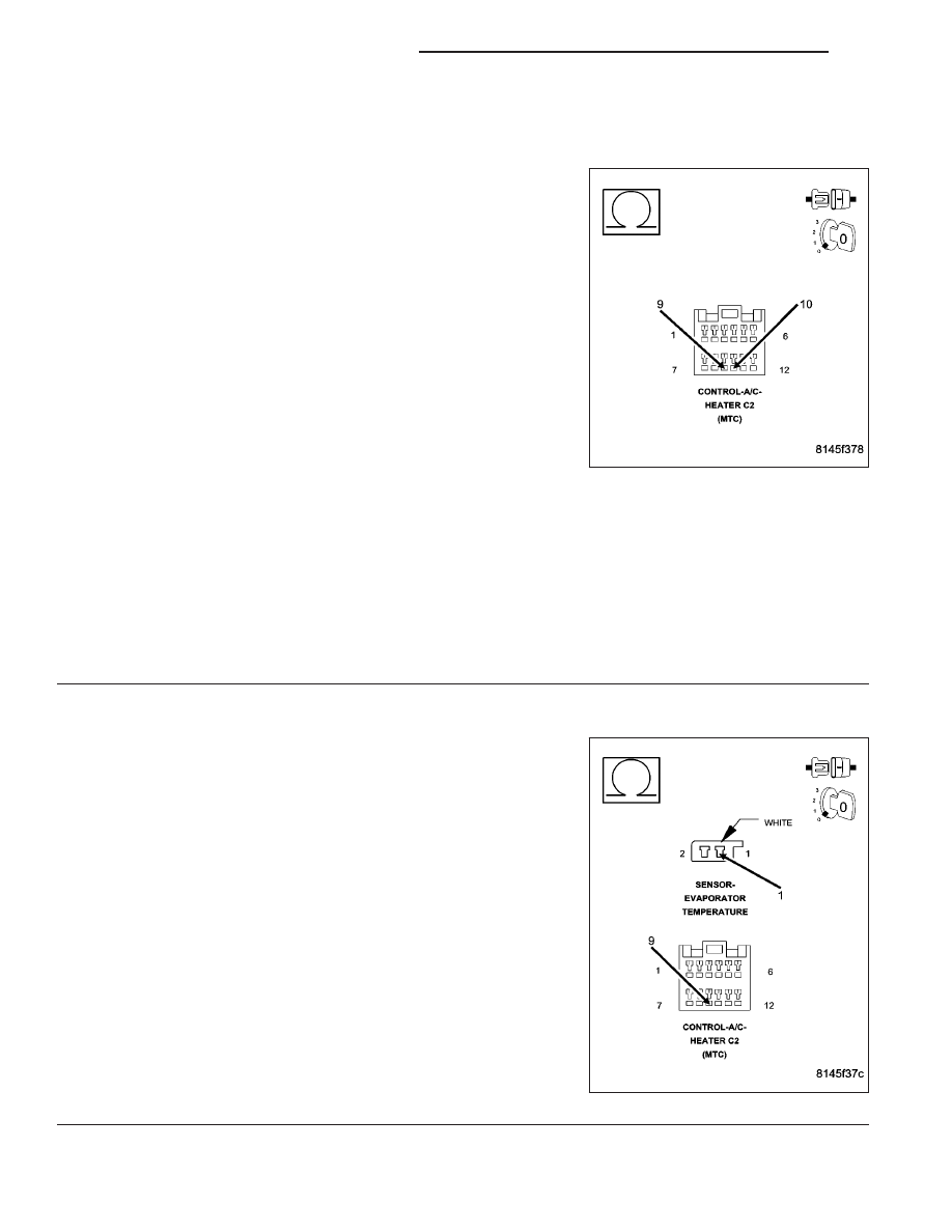
31–EVAPORATOR SENSOR OPEN (MTC) (CONTINUED)
2.
CHECK (C21) EVAPORATOR TEMPERATURE SENSOR SIGNAL CIRCUIT, (C121) SENSOR GROUND
CIRCUIT, & EVAPORATOR TEMPERATURE SENSOR
Turn the ignition off.
Measure the resistance between the (C21) Evaporator Temperature
Sensor Signal circuit and the (C121) Sensor Ground circuit in the A/C
Heater Control C2 harness connector. The approximate circuit resis-
tance should be as follows:
•
1468 ohms @ 40°C (104°F)
•
1800 ohms @ 35°C (95°F)
•
2221 ohms @ 30°C (86°F)
•
2757 ohms @ 25°C (77°F)
•
3443 ohms @ 20°C (68°F)
•
4330 ohms @ 15°C (59°F)
•
5485 ohms @ 10°C (50°F)
•
6998 ohms @ 5°C (41°F)
•
7354 ohms @ 4°C (39°F)
•
7731 ohms @ 3°C (37°F)
•
8130 ohms @ 2°C (36°F)
•
8553 ohms @ 1°C (34°F)
•
9000 ohms @ 0°C (32°F)
Is the resistance within the specifications?
Yes
>> Replace the A/C Heater Control in accordance with the Service Information.
Perform BODY VERIFICATION TEST – VER 1. (Refer to 8 - ELECTRICAL/ELECTRONIC CONTROL
MODULES - STANDARD PROCEDURE).
No
>> Go To 3
3.
CHECK (C21) EVAPORATOR TEMPERATURE SENSOR SIGNAL CIRCUIT FOR AN OPEN
Disconnect the Evaporator Temperature Sensor harness connector.
Measure the resistance of the (C21) Evaporator Temperature Sensor
Signal circuit between the Evaporator Temperature Sensor harness
connector and the A/C Heater Control C2 harness connector.
Is the resistance below 5.0 ohms?
Yes
>> Go To 4
No
>> Repair the (C21) Evaporator Temperature Sensor Signal
circuit for an open.
Perform BODY VERIFICATION TEST – VER 1. (Refer to 8
- ELECTRICAL/ELECTRONIC CONTROL MODULES -
STANDARD PROCEDURE).
24 - 28
HVAC - ELECTRICAL DIAGNOSTICS
WK