Jeep Grand Cherokee WK. Manual - part 1597


  Index      Jeep     Jeep Grand Cherokee WK - service repair manual 2005 year


Search            


Content   ..  1595  1596  1597  1598   ..


Jeep Grand Cherokee WK. Manual - part 1597


LATCH

REMOVAL

1. Raise the rear window to the full up position and

remove the rear door trim panel (Refer to 23 -
BODY/DOORS - REAR/TRIM PANEL - REMOVAL).

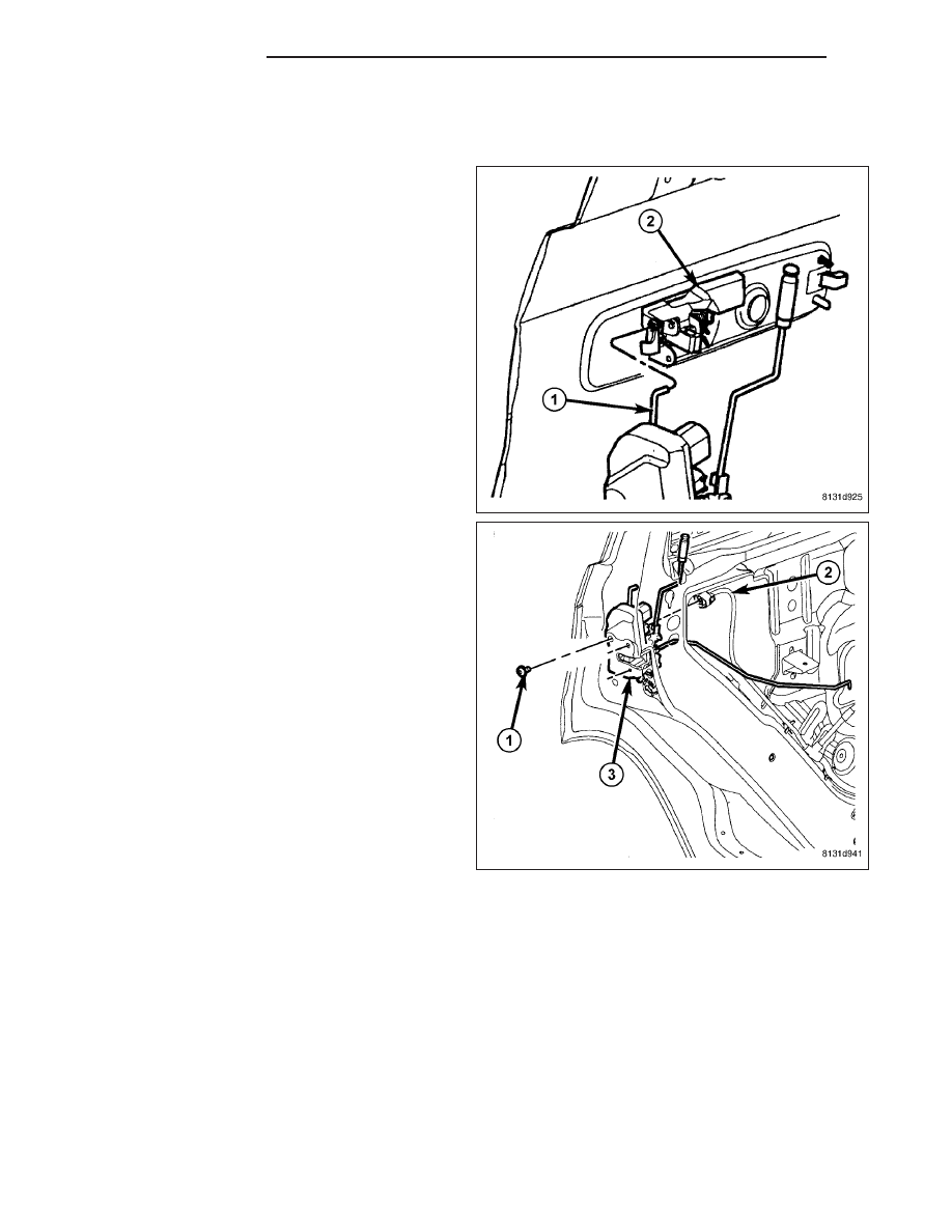
2. Position the watershield out of the way and discon-

nect the actuator rod (1) from the exterior handle
(2).

3. Disconnect the interior handle actuator rod from the

rear door latch (3) and remove the rod.

4. Disconnect the door wire harness connector (2)

from the rear door latch.

5. Remove the three bolts (1) that secure the rear

door latch to the door and remove the latch and
actuator rods as an assembly.

6. If required, remove all of the actuator rods from the

actuator.

23 - 46

DOORS - REAR

WK

INSTALLATION

1. If removed, install the actuator rods onto the rear

door latch (3) and engage the retainers.

2. Position the rear door latch and actuator rods into

the door as an assembly.

3. Install the three bolts (1) that secure the rear door

latch to the door. Tighten the bolts to 10 N·m (89
in. lbs.).

4. Connect the door wire harness connector (2) to the

rear door latch.

5. Install the interior handle actuator rod onto the rear

door latch and engage the retainer.

6. Connect the actuator rod (1) to the rear exterior

handle (2).

7. Reposition the watershield to the rear door and

install the door trim panel (Refer to 23 - BODY/
DOORS - REAR/TRIM PANEL - INSTALLATION).

8. If necessary, adjust the rear door latch (Refer to 23

-

BODY/DOORS

-

REAR/LATCH

-

ADJUSTMENTS).

WK

DOORS - REAR

23 - 47

ADJUSTMENTS

ADJUSTMENT

1. Locate the access hole in the door to adjust the

door latch (1) and remove the mylar tape (2).

2. Loosen the adjustment screw (3).

3. Operate the door handles several times to reduce

any possible linkage binding and tighten the adjust-
ment screw to 3 N·m (30 in. lbs.).

4. Operate the door handle again to verify proper

operation and reinstall the mylar tape.

PANEL-TRIM

REMOVAL

CAUTION: Door panel retention clips are designed
to be used only once. Retention clips should be
discarded and replaced with new clips each time
the door trim panel is removed from the door. Fail-
ure to replace retention clips will result in poor
door panel retention and possible customer dis-
satisfaction.

1. Disconnect and isolate the battery negative cable.

2. Remove the two screws (2) that secure the rear

door trim panel (1) to the door.

3. Carefully pull the rear door trim panel far away

enough from the door to disengage the six plastic
door trim panel retention clips (3) from the door.

4. Lift the rear of the panel upward slightly to disen-

gage the interior door latch lock link and knob from
the rear of the door panel.

23 - 48

DOORS - REAR

WK

5. Position the rear door trim panel far enough away

to access the door panel wire harness connector
(1) and the interior door handle actuator rod (2).

6. Disconnect the interior door handle actuator rod

from the interior door handle.

7. Disconnect the wire harness connector (3) from the

power door switch assembly.

8. Remove and discard the six plastic door trim panel

retention clips.

INSTALLATION

CAUTION: Door panel retention clips are designed
to be used only once. Retention clips should be
discarded and replaced with new clips each time
the door trim panel is removed from the door. Fail-
ure to replace retention clips will result in poor
door panel retention and possible customer dis-
satisfaction.

1. Install six new plastic door trim panel retention clips

onto the inside of the rear door trim panel.

2. Position the door trim panel near the rear door and

connect the door wire harness connector (3) to the
power door switch assembly (1).

3. Connect the interior door handle actuator rod (3) to

the interior door handle and engage the retainer.

4. Lift the rear trim panel (1) over the inside of the

door far enough to engage the interior door latch
lock link and knob into the hole at the upper rear
corner of the trim panel.

5. Position the trim panel to the inside of the door and

fully engage the new plastic door trim panel reten-
tion clips (3) to the door.

6. Install the two screws (2) that secure door trim

panel to the door. Tighten the screws to 2 N·m (16
in. lbs.).

7. Reconnect the negative battery cable.

WK

DOORS - REAR

23 - 49


Content   ..  1595  1596  1597  1598   ..