Content .. 1521 1522 1523 1524 ..
Jeep Grand Cherokee WK. Manual - part 1523
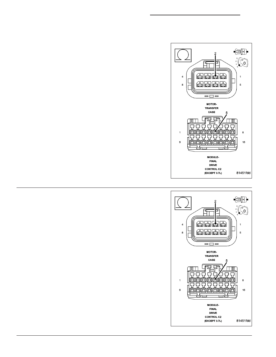
C1403-TRANSFER CASE RANGE POSITION SENSOR PERFORMANCE (CONTINUED)
6.
(T313) MODE SENSOR SIGNAL CIRCUIT HIGH RESISTANCE
Turn the ignition off.
Disconnect the Final Drive Control Module C2 harness connector.
Measure the resistance of the (T313) Mode Sensor Signal circuit.
Is the resistance above 5.0 ohms?
Yes
>> Repair the high resistance in the (T313) Mode Sensor Sig-
nal circuit.
Perform the TRANSFER CASE VERIFICATION TEST-
VER 1.
No
>> Go to 7
7.
(T313) MODE SENSOR SIGNAL CIRCUIT SHORTED TO
GROUND
Measure the resistance between ground and the (T313) Mode Sensor
Signal circuit.
Is the resistance below 5.0 ohms?
Yes
>> Repair the (T313) Mode Sensor Signal circuit for a short to
ground.
Perform the TRANSFER CASE VERIFICATION TEST-
VER 1.
No
>> Go to 8
21 - 902
TRANSFER CASE - ELECTRICAL DIAGNOSTICS
WK