Content .. 1420 1421 1422 1423 ..
Jeep Grand Cherokee WK. Manual - part 1422
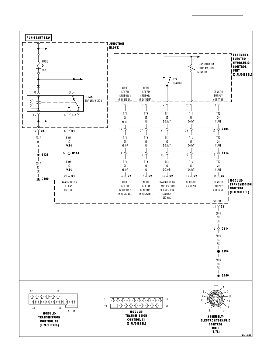
P0717-INPUT SPEED SENSOR 1 CIRCUIT NO SIGNAL
21 - 498
AUTOMATIC TRANSMISSION NAG1 - ELECTRICAL DIAGNOSTICS
WK
|
|
|
Content .. 1420 1421 1422 1423 ..
P0717-INPUT SPEED SENSOR 1 CIRCUIT NO SIGNAL 21 - 498 AUTOMATIC TRANSMISSION NAG1 - ELECTRICAL DIAGNOSTICS WK |