Content .. 1299 1300 1301 1302 ..
Jeep Grand Cherokee WK. Manual - part 1301
P2779–AUTOSTICK DOWNSHIFT SWITCH CIRCUIT PERFORMANCE
For the Transmission circuit diagram (Refer to 21 - TRANSMISSION/TRANSAXLE/AUTOMATIC - NAG1 - SCHE-
MATICS AND DIAGRAMS)
For a complete wiring diagramRefer to Section 8W
Theory of Operation
The AutoStick Switch is integrated into the Shift Lever Assembly. The gear requested by the AutoStick selection in
then sent over the CAN C bus to the TCM to engage the requested gear.
•
When Monitored:
When in AutoStick mode.
•
Set Condition:
When the expected switch state is not correctly sensed by the Shift Lever Assembly. If the upshift switch signal
is detected as active in gear position other than drive or both upshift and downshift signals are active at the
same time.
Possible Causes
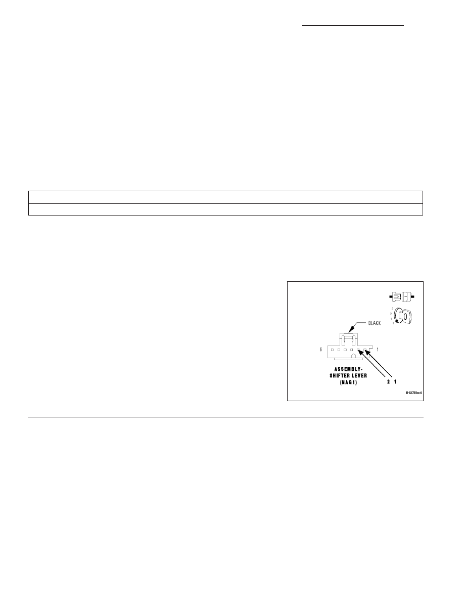
SHIFTER LEVER ASSEMBLY
Always perform the Pre-Diagnostic Troubleshooting procedure before proceeding. (Refer to 21 - TRANSMIS-
SION/TRANSAXLE/AUTOMATIC - NAG1 - DIAGNOSIS AND TESTING)
1.
SHIFTER LEVER ASSEMBLY
Using the schematics as a guide, inspect the wiring and connectors.
Repair as necessary. Pay particular attention to all power and ground
circuits.
If there are no possible causes remaining, view repair.
Repair
Using the schematics as a guide, check the Shifter Lever
Assembly Control Module terminals for corrosion, damage,
or terminal push out. Pay particular attention to all power
and ground circuits. If no problems are found, replace the
Shift Lever Assembly per the Service Information. Refer to
Shift Mechanism for the appropriate service procedures.
Perform NAG1 TRANSMISSION VERIFICATION TEST -
VER 1.
21 - 14
AUTOMATIC TRANSMISSION NAG1 - SHIFTER DIAGNOSTICS
WK