Jeep Grand Cherokee WK. Manual - part 129


  Index      Jeep     Jeep Grand Cherokee WK - service repair manual 2005 year


Search            


Content   ..  127  128  129  130   ..


Jeep Grand Cherokee WK. Manual - part 129


C100A–LEFT FRONT WHEEL SPEED SENSOR CIRCUIT (CONTINUED)

13.

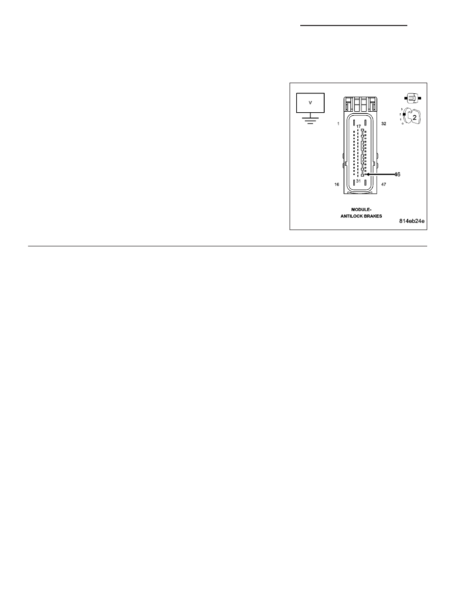
CHECK THE (B8) LEFT FRONT WSS SIGNAL VOLTAGE AT THE ANTI-LOCK BRAKE MODULE
HARNESS CONNECTOR

Turn the ignition off.

Turn the ignition on.

While back probing, measure the voltage between the (B8) Left Front
WSS Signal circuit at the Anti-Lock Brake Module harness connector
and ground.

Slowly rotate the wheel by hand.

Does the (B8) Left Front WSS Signal circuit voltage toggle
between approximately 1.6 and .8 volts?

Yes

>> Replace the Anti-Lock Brake Module in accordance with

the Service Information.

Perform ABS VERIFICATION TEST - VER 1.

No

>> Repair the (B8) Left Front WSS Signal circuit for an open.

Perform ABS VERIFICATION TEST - VER 1.

5 - 142

BRAKES - BRAKE CONTROLLER ELECTRICAL DIAGNOSTICS

WK

C1011-LEFT FRONT WHEEL SPEED SENSOR SIGNAL ERRATIC PERFORMANCE

WK

BRAKES - BRAKE CONTROLLER ELECTRICAL DIAGNOSTICS

5 - 143

C1011-LEFT FRONT WHEEL SPEED SENSOR SIGNAL ERRATIC PERFORMANCE (CONTINUED)

For the Anti-Lock Brake System circuit diagram. (Refer to 5 - BRAKES - SCHEMATICS AND DIAGRAMS)

For a complete wiring diagram Refer to Section 8W.

When Monitored:
With the ignition on.

Set Condition:
When the Left Front Wheel Speed Signal circuit indicates continuously too high or too low wheel speed.

Possible Causes

TERMINAL/CONNECTOR/TONE WHEEL DAMAGE

(B8) LEFT FRONT WSS SIGNAL CIRCUIT SHORTED TO THE (B9) LEFT FRONT WSS SUPPLY CIRCUIT

(B9) LEFT FRONT WSS SUPPLY CIRCUIT SHORTED TO VOLTAGE, GROUND, OR OPEN

(B8) LEFT FRONT WSS SIGNAL CIRCUIT SHORTED TO VOLTAGE, GROUND, OR OPEN

LEFT FRONT WHEEL SPEED SENSOR

ANTI-LOCK BRAKE MODULE

Diagnostic Test

1.

CHECK FOR A DTC C1011-LEFT FRONT WHEEL SPEED SENSOR SIGNAL ERRATIC PERFORMANCE

NOTE: This DTC must be active for the results of this test to be valid.
Turn the ignition on.

With the scan tool, read DTCs.

Record DTC and Freeze Frame information.

With the scan tool, erase DTCs.

CAUTION: Ensure braking capability is available before road testing.
Drive the vehicle over 25 km/h (15 mph).

Park the vehicle and cycle the ignition switch from off to on.

With the scan tool, read DTCs.

Does the scan tool display: C1011-LEFT FRONT WHEEL SPEED SENSOR SIGNAL ERRATIC PERFOR-
MANCE?

Yes

>> Go To 2

No

>> Refer to the INTERMITTENT CONDITION diagnostic procedure.

Perform ABS VERIFICATION TEST - VER 1.

5 - 144

BRAKES - BRAKE CONTROLLER ELECTRICAL DIAGNOSTICS

WK

C1011-LEFT FRONT WHEEL SPEED SENSOR SIGNAL ERRATIC PERFORMANCE (CONTINUED)

2.

CHECK THE TERMINALS/CONNECTORS/TONE WHEEL FOR DAMAGE

NOTE: Check all related wiring for bruised, chafed, pierced, or partially broken wires.

NOTE: Check all related connectors for broken, bent, pushed out, or corroded terminals.

NOTE: Check the tone wheel teeth for missing teeth, cracks, or looseness. Teeth should be perfectly
square, not bent, or nicked.
Turn the ignition off.

Inspect the Anti-Lock Brake Module harness connector, Left Front WSS, Left Front WSS harness connector, and
Left Front WSS tone wheel (if applicable).

Were any problems found?

Yes

>> Repair as necessary.

Perform ABS VERIFICATION TEST - VER 1.

No

>> Go To 3

3.

(B8) LEFT FRONT WSS SIGNAL CIRCUIT SHORTED TO THE (B9) LEFT FRONT WSS SUPPLY CIRCUIT

Turn the ignition off.

Disconnect the Anti-Lock Brake Module harness connector.

Disconnect the Left Front WSS harness connector.

Measure the resistance between the (B8) Left Front WSS Signal and
the (B9) Left Front WSS Supply circuits at the Left Front WSS harness
connector.

Is the resistance above 5.0 ohms?

Yes

>> Go To 4

No

>> Repair the (B8) Left Front WSS Signal circuit for a short to

the (B9) Left Front WSS Supply circuit.

Perform ABS VERIFICATION TEST - VER 1.

4.

CHECK THE VOLTAGE ON THE (B9) LEFT FRONT WSS SUPPLY CIRCUIT

Turn the ignition off.

Connect the Anti-Lock Brake Module harness connector.

Turn the ignition on.

Measure the voltage of the (B9) Left Front WSS Supply circuit in the
Left Front WSS harness connector.

Is the voltage above 10 volts?

Yes

>> Go To 8

No

>> Go To 5

WK

BRAKES - BRAKE CONTROLLER ELECTRICAL DIAGNOSTICS

5 - 145


Content   ..  127  128  129  130   ..