Jeep Grand Cherokee WK. Manual - part 118


  Index      Jeep     Jeep Grand Cherokee WK - service repair manual 2005 year


Search            


Content   ..  116  117  118  119   ..


Jeep Grand Cherokee WK. Manual - part 118


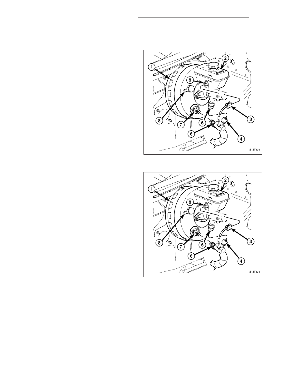
SENSOR-BRAKE PRESSURE

REMOVAL

1. Disconnect wiring harness (4) connector from pres-

sure switch (5).

2. Remove pressure switch (5) on bottom of master

cylinder.

INSTALLATION

1. Install pressure switch (5) on bottom of master cyl-

inder. Tighten switch to 28 N·m (250 in. lbs.)
torque.

2. Connect wiring harness (4) connector to pressure

switch (5).

3. Fill master cylinder fluid reservoir (2) with clean,

fresh Mopar

T

Brake Fluid or equivalent.

4. Perform Verification Test and clear any faults.

(Refer

to

5

-

BRAKES

-

DIAGNOSIS AND

TESTING).

5 - 98

BRAKES - ABS - SERVICE INFORMATION

WK

SENSOR-DYNAMICS

DESCRIPTION

The Yaw Rate and Lateral Acceleration Sensors are
housed into one unit known as the Dynamics Sensor
(1). The sensor is used to measure side-to-side (Lat-
eral) motion and vehicle rotational sensing (how fast
the vehicle is turning - Yaw).

Yaw and Lateral Acceleration Sensors cannot be ser-
viced separately. The entire Dynamics Sensor (1)
must be replaced when necessary.

REMOVAL

1. Remove the center console (Refer to 23 - BODY/

INTERIOR/FLOOR CONSOLE - REMOVAL).

2. Disconnect

electrical

connector

(3)

from

the

dynamics sensor (1).

3. Remove the two nuts (2) securing the sensor to the

floor.

4. Remove the sensors.

WK

BRAKES - ABS - SERVICE INFORMATION

5 - 99

INSTALLATION

1. Install the dynamics sensor (1) to the vehicle.

2. Install the electrical connector (3)

3. Install the two retaining nuts (2).

4. Install the floor console.

SENSOR-STEERING ANGLE

DESCRIPTION

Under transient cornering conditions the lateral acceleration sensor does not measure the true sway force on the
car. In order to compensate for this the system uses the driver’s steering command (Steering angle sensor) and
vehicle speed to estimate the true sway force. This signal is matched with the lateral acceleration sensor signal to
ensure a significantly-reduced transient sway of the vehicle body.

REMOVAL

1. For removal of the steering angle sensor (Refer to 19 - STEERING/COLUMN/STEERING CONTROL MODULE

- REMOVAL).

INSTALLATION

1. For installation of the steering angle sensor (Refer to 19 - STEERING/COLUMN/STEERING CONTROL MOD-

ULE - INSTALLATION).

5 - 100

BRAKES - ABS - SERVICE INFORMATION

WK

SENSOR-G

DESCRIPTION

G-SENSOR - WITH ESP

The G-sensor is housed internally in with the dynam-
ics sensor (1) located under the center console. The
dynamics sensor component can be replaced as one
component only. The G-sensor is not serviceable
separately.

G-SENSOR - WITHOUT ESP

The G-sensor is located inside the ABM (Antilock
Brake Module) (1). The sensor is not a separate ser-
viceable part from the ABM (1).

WK

BRAKES - ABS - SERVICE INFORMATION

5 - 101


Content   ..  116  117  118  119   ..