Content .. 1136 1137 1138 1139 ..
Jeep Grand Cherokee WK. Manual - part 1138
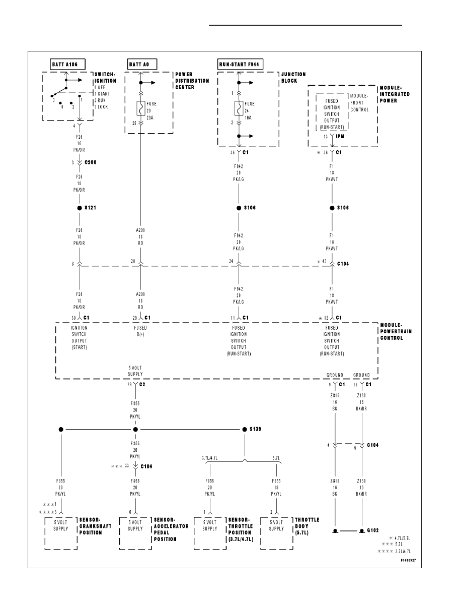
*NO RESPONSE WITH A NO START CONDITION
9 - 1148
ENGINE ELECTRICAL DIAGNOSTICS
WK
|
|
|
Content .. 1136 1137 1138 1139 ..
*NO RESPONSE WITH A NO START CONDITION 9 - 1148 ENGINE ELECTRICAL DIAGNOSTICS WK |