Content .. 1120 1121 1122 1123 ..
Jeep Grand Cherokee WK. Manual - part 1122
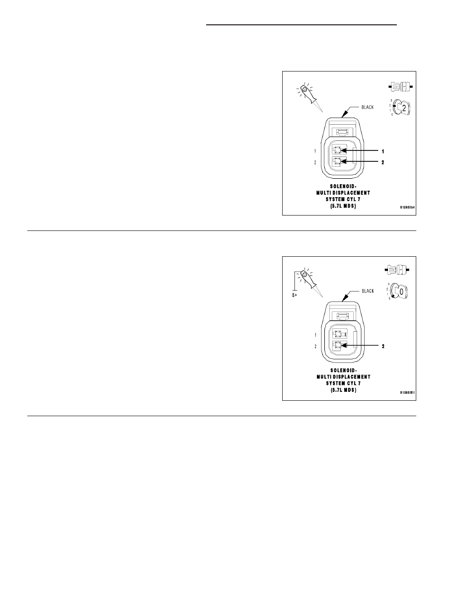
P3449-MDS SOLENOID 7 CIRCUIT (CONTINUED)
2.
MDS SOLENOID NO.7
Turn the ignition off.
Gain access to the MDS Solenoid No.7.
Disconnect the MDS Solenoid No.7 harness connector.
Ignition on, engine not running.
Turn off all accessories.
Using a 12-volt test light connected to the (Z42) Ground circuit, probe
the (K454) MDS Solenoid No.7 Control circuit.
With a scan tool, actuate the MDS Solenoid No.7.
Does the 12-volt test light flash on and off?
Yes
>> Replace the MDS Solenoid No.7.
Perform the POWERTRAIN VERIFICATION TEST. (Refer
to 9 - ENGINE - STANDARD PROCEDURE)
No
>> Go To 3
3.
(Z42) GROUND CIRCUIT OPEN
Turn the ignition off.
Using a 12-volt test light connected to the 12-volts, probe the (Z42)
Ground circuit in the MDS Solenoid No.7 harness connector.
Does the test light illuminate brightly?
Yes
>> Go To 4
No
>> Repair the open in the (Z42) Ground circuit.
Perform the POWERTRAIN VERIFICATION TEST. (Refer
to 9 - ENGINE - STANDARD PROCEDURE)
9 - 1084
ENGINE ELECTRICAL DIAGNOSTICS
WK