Content .. 1070 1071 1072 1073 ..
Jeep Grand Cherokee WK. Manual - part 1072
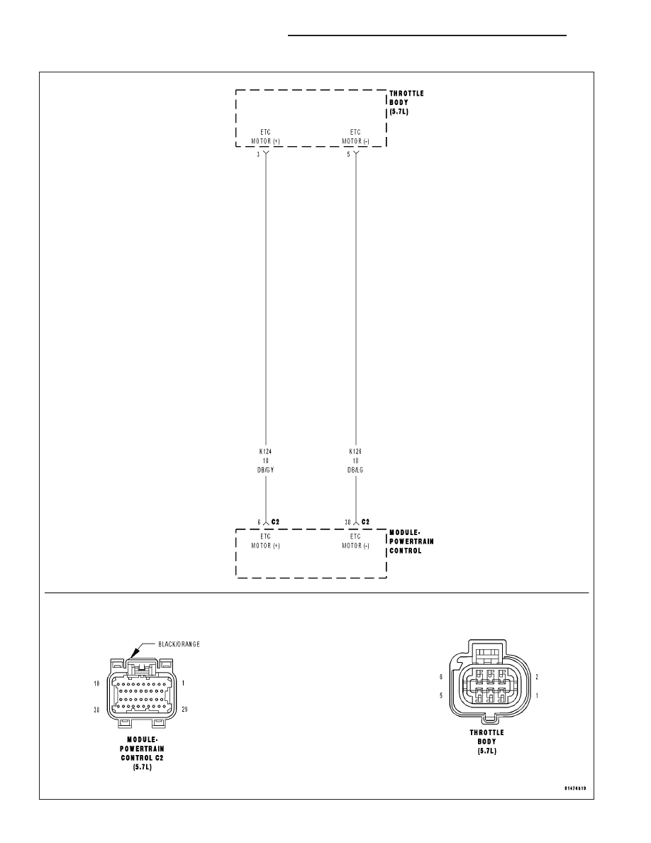
P2100-ELECTRONIC THROTTLE CONTROL MOTOR CIRCUIT
9 - 884
ENGINE ELECTRICAL DIAGNOSTICS
WK
|
|
|
Content .. 1070 1071 1072 1073 ..
P2100-ELECTRONIC THROTTLE CONTROL MOTOR CIRCUIT 9 - 884 ENGINE ELECTRICAL DIAGNOSTICS WK |