Content .. 1056 1057 1058 1059 ..
Jeep Grand Cherokee WK. Manual - part 1058
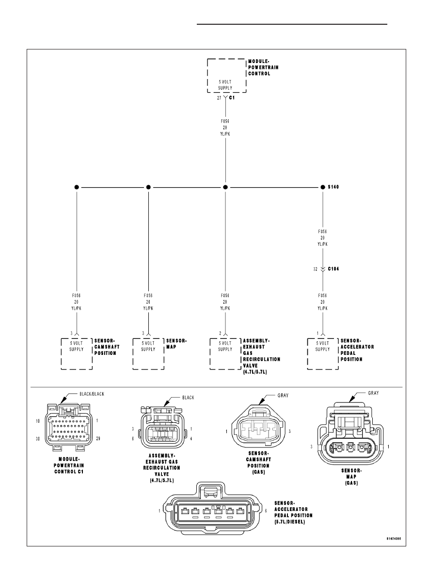
P1628-SENSOR REFERENCE VOLTAGE 2 CIRCUIT ERRATIC
9 - 828
ENGINE ELECTRICAL DIAGNOSTICS
WK
|
|
|
Content .. 1056 1057 1058 1059 ..
P1628-SENSOR REFERENCE VOLTAGE 2 CIRCUIT ERRATIC 9 - 828 ENGINE ELECTRICAL DIAGNOSTICS WK |