Jeep Grand Cherokee WK. Manual - part 1014


  Index      Jeep     Jeep Grand Cherokee WK - service repair manual 2005 year


Search            


Content   ..  1012  1013  1014  1015   ..


Jeep Grand Cherokee WK. Manual - part 1014


P0586-SPEED CONTROL VACUUM CONTROL CIRCUIT (CONTINUED)

8.

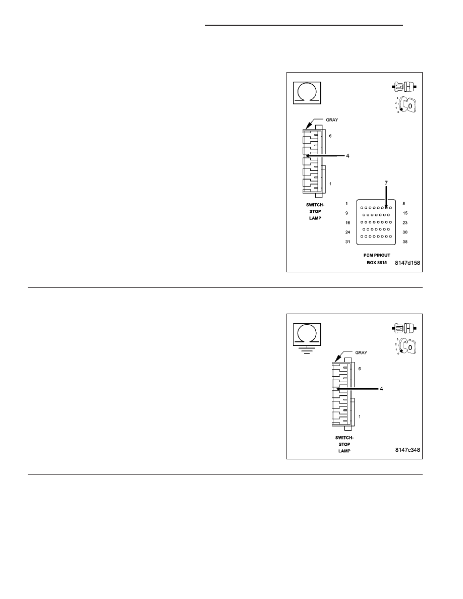
(V32) S/C SUPPLY OPEN

Turn the ignition off.

Disconnect the C3 PCM harness connector.

CAUTION: Do not probe the PCM harness connectors. Probing
the PCM harness connectors will damage the PCM terminals
resulting in poor terminal to pin connection. Install Miller Special
Tool #8815 to perform diagnosis.
Measure the resistance of the (V32) S/C Supply circuit from the Stop
Lamp Switch harness connector to the appropriate terminal of special
tool #8815.

Is the resistance below 5.0 ohms?

Yes

>> Go To 9

No

>> Repair the open/high resistance in the (V32) S/C Supply

circuit.

Perform the POWERTRAIN VERIFICATION TEST. (Refer
to 9 - ENGINE - STANDARD PROCEDURE)

9.

(V32) S/C SUPPLY CIRCUIT SHORTED TO GROUND

Measure the resistance between ground and the (V32) S/C Supply cir-
cuit at the Speed Control Servo harness connector.

Is the resistance below 100 ohms?

Yes

>> Repair the short to ground in the (V32) S/C Supply circuit.

Perform the POWERTRAIN VERIFICATION TEST. (Refer
to 9 - ENGINE - STANDARD PROCEDURE)

No

>> Go To 10

9 - 652

ENGINE ELECTRICAL DIAGNOSTICS

WK

P0586-SPEED CONTROL VACUUM CONTROL CIRCUIT (CONTINUED)

10.

PCM

NOTE: Before continuing, check the PCM harness connector terminals for corrosion, damage, or terminal
push out. Repair as necessary.

Were there any problems found?

Yes

>> Repair as necessary.

Perform the POWERTRAIN VERIFICATION TEST. (Refer to 9 - ENGINE - STANDARD PROCEDURE)

No

>> Replace and program the Powertrain Control Module per Service Information.

Perform the POWERTRAIN VERIFICATION TEST. (Refer to 9 - ENGINE - STANDARD PROCEDURE)

WK

ENGINE ELECTRICAL DIAGNOSTICS

9 - 653

P0585-SPEED CONTROL SWITCH 1/2 CORRELATION

9 - 654

ENGINE ELECTRICAL DIAGNOSTICS

WK

P0585-SPEED CONTROL SWITCH 1/2 CORRELATION (CONTINUED)

For the Engine circuit diagram (Refer to 9 - ENGINE - SCHEMATICS AND DIAGRAMS).

For a complete wiring diagram Refer to Section 8W.

When Monitored:
Ignition on.

Set Condition:
Cruise Switch inputs are not coherent with each other. Example: PCM is reading Switch No.1 as Accel and
Switch No.2 as Coast at the same time. One trip fault.

Possible Causes

S/C SWITCH SIGNAL CIRCUITS SHORTED TO BATTERY VOLTAGE

RESISTANCE IN THE S/C SWITCH SIGNAL CIRCUITS

RESISTANCE IN THE (V397/V937) SWITCH RETURN CIRCUIT

S/C SWITCH SIGNAL CIRCUITS SHORTED TO THE (V397/V937) SWITCH RETURN CIRCUIT

(V371/V71) S/C SWITCH NO.1 SIGNAL CIRCUIT SHORTED TO THE (V372/V72) S/C SWITCH NO.2 SIGNAL
CIRCUIT

S/C SWITCH SIGNAL CIRCUITS SHORTED TO GROUND

STEERING COLUMN CONTROL MODULE

SPEED CONTROL ON/OFF SWITCH

SPEED CONTROL RESUME/ACCEL SWITCH

PCM

Always perform the Pre-Diagnostic Troubleshooting procedure before proceeding. (Refer to 9 - ENGINE -
DIAGNOSIS AND TESTING).

Diagnostic Test

1.

ACTIVE DTC

Ignition on, engine not running.

NOTE: This DTC may be the result of pressing two Speed Control Switch buttons simultaneously for more
than 450 msec.
Ask the customer if it is possible that two buttons were pressed at the same time before this DTC set. If this is the
case, no repair is necessary.

Is the DTC active a this time?

Yes

>> Go To 2

No

>> Refer to the INTERMITTENT CONDITION Diagnostic Procedure.

Perform the POWERTRAIN VERIFICATION TEST. (Refer to 9 - ENGINE - STANDARD PROCEDURE)

2.

SPEED CONTROL ON/OFF SWITCH

With the scan tool, monitor the Speed Control Switch voltage.

Disconnect the Speed Control On/Off Switch harness connector.

Did the voltage change to above 4.8 volts?

Yes

>> Replace the Speed Control On/Off Switch.

Perform the POWERTRAIN VERIFICATION TEST. (Refer to 9 - ENGINE - STANDARD PROCEDURE)

No

>> Go To 3

WK

ENGINE ELECTRICAL DIAGNOSTICS

9 - 655


Content   ..  1012  1013  1014  1015   ..