Jeep Grand Cherokee WK. Manual - part 24
REMOVAL
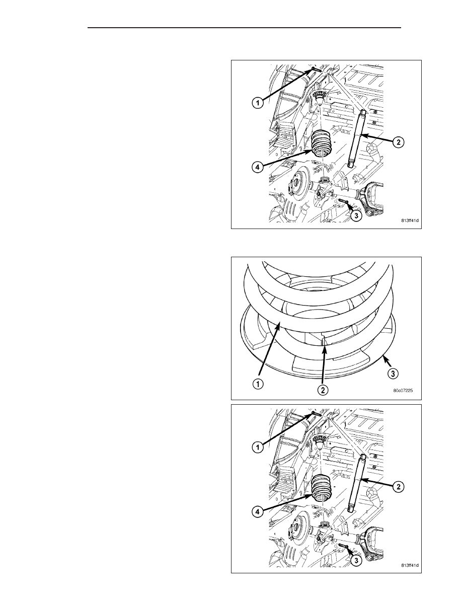
1. Raise and support the vehicle. Position a hydraulic
jack under the axle to support the axle.
2. Remove the wheel and tire assemblies.
3. Remove the lower shock bolt (3) from the axle
bracket.
4. Remove the stabilizer bar link from the body rail.
5. Lower the hydraulic jack and tilt the axle and
remove the coil spring (4).
6. Remove and inspect the spring isolators.
INSTALLATION
1. Install the upper isolator.
2. Install the lower isolator (3).
3. Pull down on the axle and position the coil spring
(1) in the lower isolator.
4. Raise the axle with the hydraulic jack.
5. Install the shock absorber (3) to the axle bracket
and tighten to 115 N·m (85 ft. lbs.).
6. Install the stabilizer bar link to the body rail, tighten
to 102 N·m (75 ft. lbs.).
7. Install the wheel and tire assemblies.
8. Remove the supports and lower the vehicle.
2 - 60
REAR
WK