Jeep Grand Cherokee WK. Manual - part 15


  Index      Jeep     Jeep Grand Cherokee WK - service repair manual 2005 year


Search            


Content   ..  13  14  15  16   ..


Jeep Grand Cherokee WK. Manual - part 15


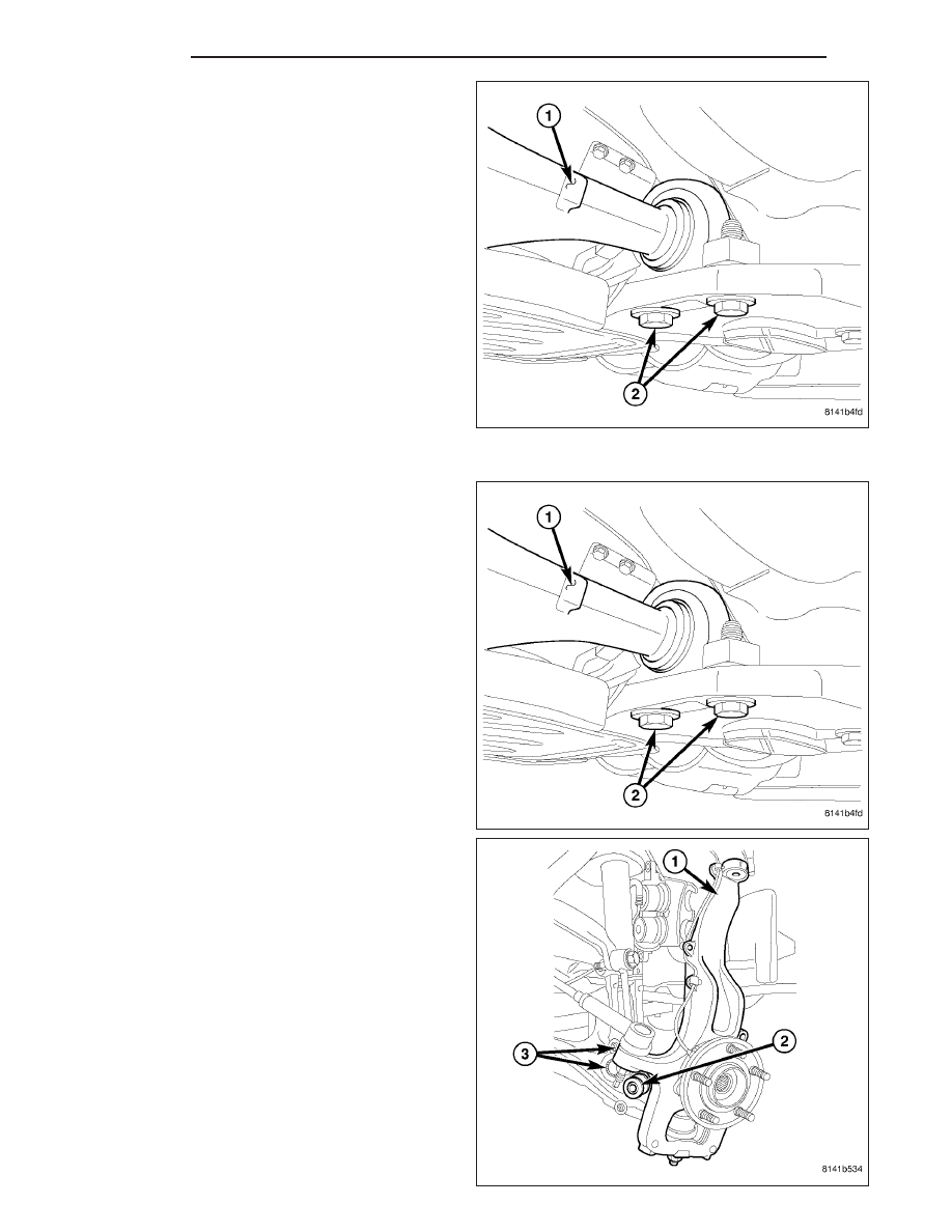
5. Remove the nut and bolt from the front of the lower

control arm.

6. Remove the rear bolts and flag nuts from the lower

control arm.

7. Remove the lower control arm from the vehicle.

INSTALLATION

1. Position the lower suspension arm into the frame

rail bracket.

2. Install the rear bolts for the lower control arm to the

frame, Tighten to 142 N·m (105 ft lbs).

3. Install the nut and bolt for the front of the lower

control arm Tighten to 169 N·m (125 ft lbs).

4. Install the lower clevis bolt (2) at the lower control

arm and tighten to 88 N·m (65 ft. lbs.).

2 - 24

FRONT

WK

5. Install the steering knuckle (3) and tighten the nut

to 75 N·m (55 ft. lbs.) (Refer to 2 - SUSPENSION/
FRONT/KNUCKLE - INSTALLATION).

6. Install the tire and wheel assembly.

7. Lower the vehicle.

8. Perform wheel alignment (Refer to 2 - SUSPENSION/WHEEL ALIGNMENT - STANDARD PROCEDURE).

SHOCK

DESCRIPTION

The top of the shock absorbers are bolted to the body. The bottom of the shocks are bolted to the lower control
arm. The standard shocks have conventional twin tube construction and are low pressure gas charged. Gas charg-
ing prevents cavitation during rough road operation.

OPERATION

The shock absorbers dampen jounce and rebound motion of the vehicle over various road conditions and limit sus-
pension rebound travel.

REMOVAL

RIGHT FRONT

1. Remove the air box cover and air intake hose.

2. Disconnect the cruise control servo electrical connector.

3. Remove the coolant reservoir mounting bolt and move the coolant reservoir off to the side.

WK

FRONT

2 - 25

4. Remove the four upper shock mounting nuts (1).

5. Raise and support the vehicle.

6. Remove the tire.

7. Remove the two brake caliper adapter bolts.

8. Support the brake caliper adaptor and caliper. Do not allow the caliper to hang by the brake hose.

9. Remove the disc brake rotor.

10. Remove the upper ball joint nut.

11. Separate the upper ball joint (2) from the knuckle

(3) using special tool 8677(1).

2 - 26

FRONT

WK

12. Remove the lower clevis bolt (2) at the lower con-

trol arm.

13. Remove the lower stabilizer bolt (3) at the lower

control arm.

14. Remove the shock from the vehicle.

15. Remove the spring if necessary (Refer to 2 -

SUSPENSION/FRONT/SPRING - REMOVAL).

LEFT FRONT

1. Remove the air box cover and air intake hose.

2. Remove the 3 PDC bracket nuts (1).

WK

FRONT

2 - 27


Content   ..  13  14  15  16   ..