Jeep Grand Cherokee WJ. Manual - part 707


  Index      Jeep     Jeep Grand Cherokee WJ - service repair manual 2001 year


Search            


Content   ..  705  706  707  708   ..


Jeep Grand Cherokee WJ. Manual - part 707


(12) While holding the differential case in position,

remove the differential bearing cap bolts and caps.

(13) Remove the differential from the housing.

Ensure that the differential bearing cups remain in
position on the differential bearings (Fig. 24).

(14) Remove bearing cups from the differential and

tag them to indicate their location on the differential.

(15) Remove differential case preload shims from

the housing and tag them to indicate their location in
the housing.

(16) Remove spreader from housing.

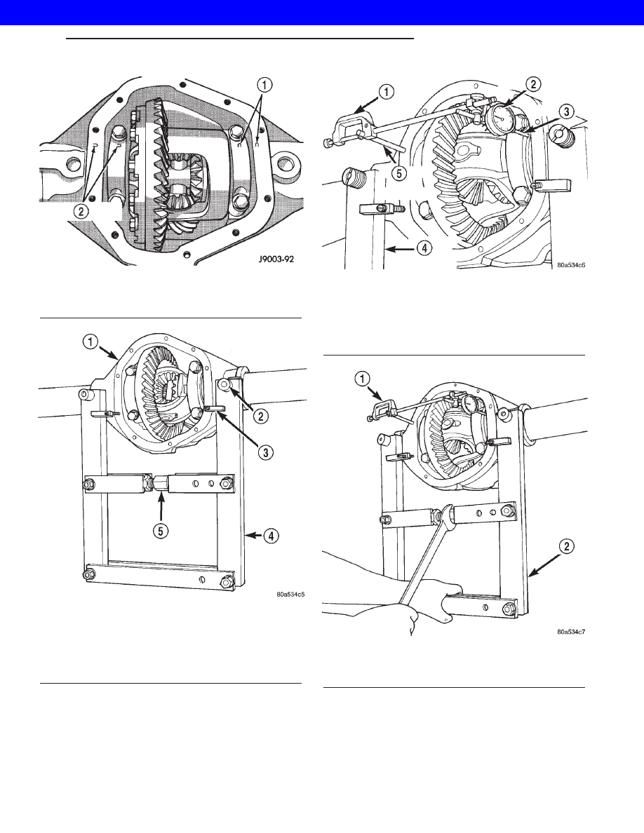
Fig. 20 Bearing Cap Identification

1 - REFERENCE LETTERS
2 - REFERENCE LETTERS

Fig. 21 Spreader Location

1 - AXLE HOUSING
2 - DOWEL
3 - SAFETY HOLD DOWN
4 - SPREADER
5 - TURNBUCKLE

Fig. 22 Dial Indicator Location

1 - CLAMP
2 - DIAL INDICATOR
3 - LEVER ADAPTER
4 - SPREADER
5 - PILOT STUD

Fig. 23 Spread Differential Housing

1 - SPECIAL TOOL C-3339
2 - SPECIAL TOOL W-129–B

WG

REAR AXLE - 198RBI

3s - 29

DIFFERENTIAL (Continued)

2001 JEEP GRAND CHEROKEE

INSTALLATION

NOTE: If replacement differential bearings or differ-
ential case are being installed, differential side
bearing shim requirements may change. Refer
Adjustments (Differential Bearing Preload and Gear
Backlash) to determine the proper shim selection.

(1) Position

Spreader

W-129-B,

utilizing

some

items from Adapter set 6987, with the tool dowel pins
seated in the locating holes (Fig. 25). Install the hold-
down clamps and tighten the tool turnbuckle finger-
tight.

(2) Install a Pilot Stud C-3288-B at the left side of

the differential housing. Attach Dial Indicator C-3339
to pilot stud. Load the indicator plunger against the
opposite side of the housing and zero the indicator.

CAUTION: Do not spread over 0.38 mm (0.015 in). If
the housing is over–spread, it could be distorted or
damaged.

(3) Spread the housing enough to install the case

in the housing. Measure the distance with the dial
indicator.

(4) Remove the dial indicator.
(5) Install differential case in the housing. Ensure

that the differential bearing cups remain in position
on the differential bearings and that the preload
shims remain between the face of the bearing cup
and the housing. Tap the differential case to ensure
the bearings cups and shims are fully seated in the
housing.

NOTE: When installing a Vari-lok™ differential the
oil feed tube must be pointed to the bottom of the
housing. If differential is installed with the oil feed
tube pointed toward the top, the anti-rotation tabs
will be damaged.

(6) Install the bearing caps in their original loca-

tions (Fig. 26).

(7) Loosely install differential bearing cap bolts.
(8) Remove axle housing spreader.
(9) Tighten the bearing cap bolts to 77 N·m (57 ft.

lbs.).

(10) Install the axle shafts.
(11) Apply a 6.35mm (1/4 in.) bead of Mopar

t Sil-

icone Rubber Sealant or equivalent to the housing
cover (Fig. 27).

Install the housing cover within 5 minutes

after applying the sealant.

(12) Install the cover and any identification tag.

Tighten the cover bolts in a criss-cross pattern to 41
N·m (30 ft. lbs.).

(13) Refill the differential with Mopar

t Hypoid

Gear Lubricant or equivalent to bottom of the fill
plug hole. Refer to Lubricant Specifications for cor-
rect quantity and type.

(14) Install fill hole plug.
(15) Remove support and lower the vehicle.

Fig. 24 Differential

1 - DIFFERENTIAL HOUSING
2 - DIFFERENTIAL CASE
3 - BEARING CUPS

Fig. 25 Spreader Location

1 - AXLE HOUSING
2 - DOWEL
3 - SAFETY HOLD DOWN
4 - SPREADER
5 - TURNBUCKLE

3s - 30

REAR AXLE - 198RBI

WG

DIFFERENTIAL (Continued)

2001 JEEP GRAND CHEROKEE

DIFFERENTIAL TRAC-LOCK

DIAGNOSIS AND TESTING - TRAC-LOK™

The most common problem is a chatter noise when

turning corners. Before removing a Trac-lok™ unit
for repair, drain, flush and refill the axle with the
specified lubricant. A container of Mopar Trac-lok™

Lubricant (friction modifier) should be added after
repair service or during a lubricant change.

After changing the lubricant, drive the vehicle and

make 10 to 12 slow, figure-eight turns. This maneu-
ver will pump lubricant through the clutches. This
will correct the condition in most instances. If the
chatter persists, clutch damage could have occurred.

DIFFERENTIAL TEST

The differential can be tested without removing the

differential case by measuring rotating torque. Make
sure brakes are not dragging during this measure-
ment.

(1) Place blocks in front and rear of both front

wheels.

(2) Raise one rear wheel until it is completely off

the ground.

(3) Engine off, transmission in neutral, and park-

ing brake off.

(4) Remove wheel and bolt Special Tool 6790 or

equivalent tool to studs.

(5) Use torque wrench on special tool to rotate

wheel and read rotating torque (Fig. 28).

(6) If rotating torque is less than 22 N·m (30 ft.

lbs.) or more than 271 N·m (200 ft. lbs.) on either
wheel the unit should be serviced.

DISASSEMBLY

(1) Clamp side gear Holding Fixture 6965 in a vise

and position the differential case on the Holding Fix-
ture (Fig. 29).

(2) Remove ring gear if the ring gear is to be

replaced. The Trac-lok™ differential can be serviced
with the ring gear installed.

(3) Remove the pinion gear mate shaft lock screw

(Fig. 30).

Fig. 26 Bearing Cap Reference

1 - REFERENCE LETTERS
2 - REFERENCE LETTERS

Fig. 27 Differential Cover - Typical

1 - COVER
2 - SEALANT
3 - SEALANT BEAD

Fig. 28 Trac-lok™ Test -Typical

1 - SPECIAL TOOL 6790 WITH BOLT IN CENTER HOLE
2 - TORQUE WRENCH

WG

REAR AXLE - 198RBI

3s - 31

DIFFERENTIAL (Continued)

2001 JEEP GRAND CHEROKEE

(4) Remove pinion gear mate shaft with a drift and

hammer (Fig. 31).

(5) Install and lubricate Step Plate C-6960-3 (Fig.

32).

(6) Assemble Threaded Adapter C-6960-1 into top

side gear. Thread Forcing Screw C-6960-4 into
adapter until it becomes centered in adapter plate.

(7) Position

a

small

screw

driver

in

slot

of

Threaded Adapter Disc C-6960-1 (Fig. 33) to prevent
adapter from turning.

(8) Install Forcing Screw C-6960-4 and tighten

screw to 122 N·m (90 ft. lbs.) maximum to compress
Belleville springs in clutch packs (Fig. 34).

(9) With a feeler gauge remove thrust washers

from behind the pinion gears (Fig. 35).

Fig. 29 Differential Case Holding Fixture

1 - HOLDING FIXTURE
2 - VISE
3 - DIFFERENTIAL

Fig. 30 Mate Shaft Lock Screw

1 - LOCK SCREW
2 - PINION GEAR MATE SHAFT

Fig. 31 Pinion Shaft

1 - PINION MATE SHAFT
2 - SIDE GEAR
3 - DRIFT
4 - PINION MATE GEAR

Fig. 32 Step Plate

1 - LOWER SIDE GEAR
2 - DIFFERENTIAL CASE
3 - STEP PLATE

3s - 32

REAR AXLE - 198RBI

WG

DIFFERENTIAL TRAC-LOCK (Continued)

2001 JEEP GRAND CHEROKEE


Content   ..  705  706  707  708   ..