Jeep Grand Cherokee WJ. Manual - part 678
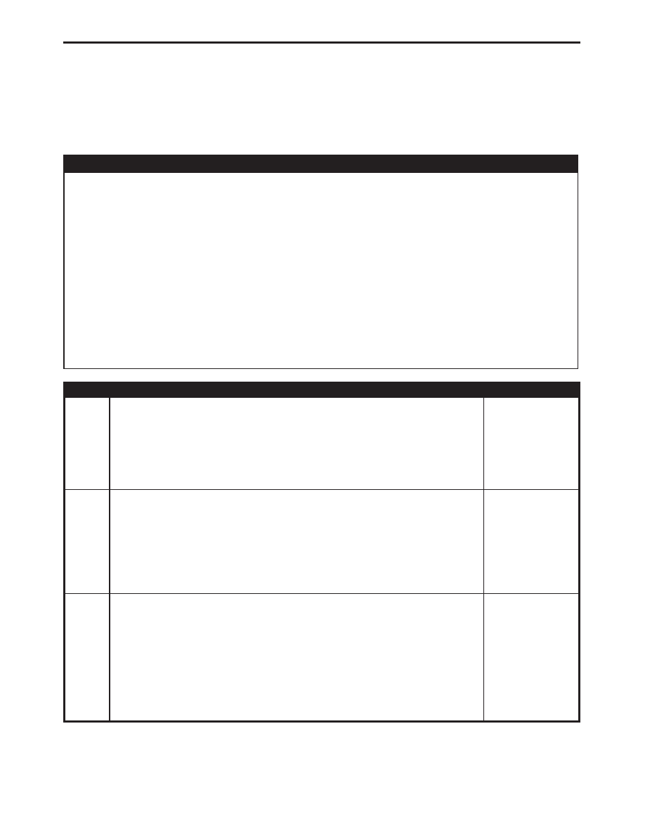
Symptom:
*CHECKING THE VEHICLE SPEED SIGNAL
POSSIBLE CAUSES
CHECK FOR CONTROLLER ANTILOCK BRAKE DTCS
CONTROLLER - ANTILOCK BRAKE
POWERTRAIN CONTROL MODULE
VEHICLE SPEED SIGNAL CIRCUIT OPEN
ENGINE CONTROL MODULE
INSTRUMENT CLUSTER
VEHICLE SPEED SIGNAL CKT BETWEEN JB AND INSTRUMENT CLUSTER SHORTED TO
GROUND
ENGINE CONTROL MODULE
JUNCTION BLOCK
VEHICLE SPEED SIGNAL CIRCUIT SHORTED TO GROUND
TEST
ACTION
APPLICABILITY
1
Turn the ignition on.
With the DRB, select Engine, JTEC then Sensors.
Note the Vehicle Speed reading on the DRB while test driving the vehicle.
Does the DRB display an accurate vehicle speed reading?
All
Yes
→
Test Complete.
No
→
2
Turn the ignition on.
With the DRB, check for Controller Antilock Brake (CAB) DTCs.
Are any CAB DTCs present?
All
Yes
→
Refer to symptom list for problems related to CAB DTCs before
continuing.
Perform ROAD TEST VERIFICATION - VER-2.
No
→
3
Turn the ignition off.
Disconnect the CAB harness connector.
Disconnect the PCM harness connectors.
Turn the ignition on.
Measure the voltage of the Vehicle Speed Signal circuit in the CAB harness
connector.
Is the voltage above 4.0 volts?
All
Yes
→
No
→
268
DRIVEABILITY - DIESEL