Jeep Grand Cherokee WJ. Manual - part 604
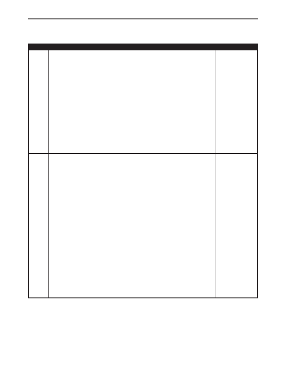
TEST
ACTION
APPLICABILITY
3
Turn the ignition off.
Inspect the Tone Wheel for damaged or missing teeth, cracks, or looseness.
Note: The Tone Wheel Teeth should be perfectly square, not bent or nicked.
Is the Tone Wheel OK?
All
Yes
→
No
→
Replace the Tone Wheel in accordance with the Service Informa-
tion.
Perform ABS VERIFICATION TEST - VER 1.
4
Turn the ignition off.
Using a Feeler Gauge, measure the Wheel Speed Sensor Air Gap.
NOTE: The Air Gap should be checked in at least four places on the Tone
Wheel.
Is the Air Gap between 0.42 mm - 1.71 mm (0.017
9 - 0.0689) ?
All
Yes
→
No
→
Repair as necessary.
Perform ABS VERIFICATION TEST - VER 1.
5
Turn the ignition off.
Inspect the wheel bearings at the affected wheel for excessive runout or clearance.
Note: Refer to the appropriate service information, if necessary, for proce-
dures or specifications.
Is the bearing clearance OK ?
All
Yes
→
No
→
Repair as necessary.
Perform ABS VERIFICATION TEST - VER 1.
6
Turn ignition off.
Disconnect the CAB harness connector.
Remove the harness strain relief to access the wires in the CAB connector.
With a voltmeter and special tool 6801, backprobe the Wheel Speed Sensor 12 volt
Supply and Signal circuits for the affected wheel at the CAB.
Reconnect the CAB.
Turn the ignition on.
Slowly rotate the right rear wheel while observing the voltmeter reading.
Does the voltage change from approximately 1.6 volts to 0.8 volts as the wheel is
rotated?
All
Yes
→
Replace the Controller Antilock Brake in accordance with the
Service Information.
Perform ABS VERIFICATION TEST - VER 1.
No
→
Replace the Right Rear Wheel Speed Sensor in accordance with
the Service Information.
Perform ABS VERIFICATION TEST - VER 1.
44
BRAKES (CAB)
RIGHT REAR SENSOR SIGNAL FAILURE —
Continued