Jeep Grand Cherokee WJ. Manual - part 527


  Index      Jeep     Jeep Grand Cherokee WJ - service repair manual 2001 year


Search            


Content   ..  525  526  527  528   ..


Jeep Grand Cherokee WJ. Manual - part 527


INSTALLATION

WARNING: REVIEW ALL WARNINGS AND CAU-
TIONS IN THIS GROUP BEFORE PRECEDING WITH
INSTALLATION.

CAUTION: Open a window before installing wind-
shield. This will avoid pressurizing the passenger
compartment. If a door or liftgate is slammed before
urethane is cured, water leaks can result.

The windshield fence should be cleaned of old ure-

thane bonding material. Support spacers should be
cleaned and properly installed on weld studs or
repair screws at bottom of windshield opening.

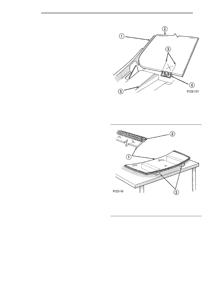
(1) Place replacement windshield into windshield

opening. Position glass in the center of the opening
against the support spacers. Mark the glass at the sup-
port spacers with a grease pencil or masking tape and
ink pen to use as a reference for installation. Remove
replacement windshield from windshield opening (Fig. 3).

(2) Position the windshield inside up on a suitable

work surface with two padded, wood 10 cm by 10 cm
by 50 cm (4 in. by 4 in. by 20 in.) blocks, placed par-
allel 75 cm (2.5 ft.) apart (Fig. 4).

(3) Clean inside of windshield with Mopar Glass

Cleaner and lint-free cloth.

(4) Apply clear glass primer 25 mm (1 in.) wide around

edge of windshield. Wipe with clean/dry lint-free cloth.

(5) Apply black-out primer 15 mm (.75 in.) wide on

top and sides of windshield and 25 mm (1 in.) on bottom
of windshield. Allow at least three minutes drying time.

(6) Position windshield spacers on lower fence

above support spacers at the edge of the windshield
opening (Fig. 1).

(7) Apply a 10 mm (0.4 in.) bead of urethane around

perimeter of windshield along the inside of the mold-
ings. Apply two beads along the bottom edge.

(8) Install upper molding onto windshield.
(9) Apply fence primer around the perimeter of the

windshield opening fence. Allow at least 18 minutes
drying time.

(10) With aid of a helper, position windshield over

windshield opening. Align reference marks at bottom
of windshield to support spacers.

(11) Slowly lower windshield glass to windshield

opening fence. Guide top molding into proper position
if necessary. Push windshield inward to fence spacers
at bottom and until top molding is flush to roof line.

(12) Clean excess urethane from exterior with

Mopar Super Clean or equivalent.

(13) Install windshield side moldings.
(14) Install cowl cover and wipers.
(15) Install inside rear view mirror.
(16) After urethane has cured, water test wind-

shield to verify repair.

QUARTER WINDOW GLASS

REMOVAL

(1) Cut urethane bonding from around quarter

window glass using a suitable sharp cold knife. A
pneumatic cutting device can be used if available.

(2) Separate glass from vehicle.

Fig. 3 Center Windshield and Mark at Support

Spacers

1 – A-PILLAR
2 – WINDSHIELD
3 – MARKS
4 – SUPPORT SPACER
5 – COWL

Fig. 4 Work Surface Set up and Molding Installation

1 – WINDSHIELD AND MOULDINGS
2 – URETHANE BEAD AROUND GLASS 7mm (.3 in.) FROM

EDGE

3 – BLOCKS

23 - 6

BODY

WJ

REMOVAL AND INSTALLATION (Continued)

INSTALLATION

CAUTION: Open a window before installing glass.
This will avoid pressurizing the passenger compart-
ment. If a door or liftgate is slammed before ure-
thane is cured, water leaks can result.

The window opening fence should be cleaned of old

urethane bonding material.

(1) Clean inside of glass with Mopar Glass Cleaner

and lint-free cloth.

(2) Apply PVC (vinyl) primer 25 mm (1 in.) wide

around edge of glass. Wipe with clean/dry lint-free cloth.

(3) Apply fence primer around edge of fence. Allow

at least eighteen minutes drying time.

(4) Apply a 10 mm (0.4 in.) bead of urethane

around window vinyl border location.
Position glass into window opening and lock clips
into place (Fig. 5).

Fig. 5 Quarter Window Glass

1 – CLIP
2 – ROOF PANEL
3 – QUARTER WINDOW GLASS

WJ

BODY

23 - 7

REMOVAL AND INSTALLATION (Continued)

POWER SUNROOF

TABLE OF CONTENTS

page

page

DESCRIPTION AND OPERATION

SUNROOF OPERATION. . . . . . . . . . . . . . . . . . . . . 8

DIAGNOSIS AND TESTING

DIAGNOSTIC PROCEDURES . . . . . . . . . . . . . . . . 8

REMOVAL AND INSTALLATION

SUNROOF WIND DEFLECTOR . . . . . . . . . . . . . . 11
SUNROOF GLASS PANEL . . . . . . . . . . . . . . . . . . 11
DRAIN TUBE . . . . . . . . . . . . . . . . . . . . . . . . . . . . 11

SUNROOF EXPRESS MODULE . . . . . . . . . . . . . . 12
SUNROOF DRIVE MOTOR. . . . . . . . . . . . . . . . . . 13
SUNROOF GLASS PANEL TIMING. . . . . . . . . . . . 13
SUNROOF SUNSHADE . . . . . . . . . . . . . . . . . . . . 13
SUNROOF HOUSING ASSEMBLY . . . . . . . . . . . . 14

ADJUSTMENTS

SUNROOF GLASS PANEL ADJUSTMENT . . . . . . 14

DESCRIPTION AND OPERATION

SUNROOF OPERATION

WARNING: Keep fingers and other body parts out
of sunroof opening at all times.

The sunroof features a power sliding glass panel and

a sunshade which can be manually positioned anywhere
along its travel, rearward of glass panel front edge.

The sunroof is electrically operated from a switch

located on the mini overhead console. To operate the
sunroof the ignition switch must be in the On/Run
position. The sunroof has both manual and Express
Open modes of operation when opening. To open the
sunroof in the Express Open mode, the switch is
pressed rearward for less than 1 second. This causes
the sunroof glass to automatically retract and stop at
a position slightly forward of full open that reduces
low speed wind buffeting. The sunroof can also be
opened manually by pressing and holding the switch
rearward. Once the switch is held reward for more
than 1 second, the glass will retract in the manual
mode. Releasing the switch at any time during travel
will cause the sunroof to stop at the current position.

To close the sunroof from an open position, the

switch must be pushed forward and held until the
sunroof glass comes to a complete stop. Releasing the
switch at any time in this mode will cause the sun-
roof to stop at the current position.

To vent the sunroof from the closed position, the

switch is pushed forward and held. Releasing the
switch at any time during travel will cause the sun-
roof to stop at the current vent position. To reach the
fully vented position, continue to hold the switch for-
ward until vent motion stops. To close the sunroof
from the vent position, push and hold the switch
rearward until the glass comes to a complete stop.

DIAGNOSIS AND TESTING

DIAGNOSTIC PROCEDURES

CAUTION: The sunroof motor is only to be pow-
ered through the vehicle battery and vehicle wire
harness. Applying power to the sunroof motor leads
will cause failure of the sunroof control unit.

Before beginning sunroof diagnostics verify that all

other power accessories are in proper operating condition.
Refer to Sunroof Diagnostic Chart for possible causes. If
not, a common electrical problem may exist. Refer to
Group 8W, Wiring Diagrams, of this publication for circuit,
splice and component descriptions. Check the condition of
the circuit protection (20 amp high current fuse (battery
feed) located in the Power Distribution Center (PDC).
Check the cover of the PDC for location of the fuse. Check
for correct operation of the sunroof delay relay. Inspect all
wiring connector pins for proper engagement and continu-
ity. Check for battery voltage at battery and ignition pins
of the power sunroof express module wiring connector.
Refer to Group 8W, Wiring Diagrams, for circuit informa-
tion. The controller will not operate at less than 10 volts.
Check the ground at the sunroof express module.

Before beginning diagnosis for wind noise or water

leaks, verify that the problem was not caused by
releasing the control switch before the sunroof was
fully closed. The sunroof module has a water-man-
agement

system.

During

washing

high-pressure

water may be forced between the glass panel seal
and the roof opening. Normally this water will drain.
However, when some type of drying blower system is
used, like those found in automatic car washes, the
water may not have a chance to drain before the
blower forces air between the seal and the roof open-
ing. This causes the water to blow over the edge of
the module and onto the headlining.

Refer to (Fig. 1) Sunroof Assembly for exploded

view of the sunroof.

23 - 8

BODY

WJ

SUNROOF DIAGNOSIS CHART

SYMPTOM

POSSIBLE CAUSE

Sunroof motor inoperative.

Faulty control switch.
Faulty circuit ground between sunroof express module, drive
motor, control switch, and body harness.
Faulty power circuit between sunroof express module, drive
motor, switch, and body harness.
Faulty sunroof drive motor.
Faulty sunroof express module.
Faulty sunroof drive motor connector.

Audible whine when switch is depressed,
sunroof does not operate.

Faulty sunroof drive motor.
Binding cable.

Audible clicking or ratcheting when switch is
pressed, sunroof does not operate.

Broken or worn drive cable.
Worn drive motor gear.
Mechanisms not synchronized.

Sunroof vents and opens, but does not close.

Binding cable.
Faulty circuit.
Faulty control switch.
Faulty sunroof express module.
Faulty drive motor.

Sunroof vents, but does not open.

Binding linkage.
Faulty circuit.
Faulty switch.
Faulty sunroof controller.
Faulty drive motor.

Sunroof does not vent

Binding cable.
Faulty circuit.
Faulty control switch.
Faulty sunroof express module.

Sunroof water leak.

Drain tubes cut, disconnected,clogged or kinked.
Drain tube grommet loose at floorpan.
Glass panel improperly adjusted.
Faulty glass panel seal.

Wind noise from sunroof.

Front of glass panel too high or rear too low.
Glass panel not centered in opening.
Faulty glass panel seal.
Roof rack crossbar to close to rear of suroof opening.

Rattles from open sunroof while driving

Loose or broken attaching hardware.
Worn or broken mechanism.

Rattles from closed sunroof while driving

Loose or broken attaching hardware.
Worn or broken mechanism.
Loose wiring or wiring components.

WJ

BODY

23 - 9

DIAGNOSIS AND TESTING (Continued)


Content   ..  525  526  527  528   ..