Jeep Grand Cherokee WJ. Manual - part 517


  Index      Jeep     Jeep Grand Cherokee WJ - service repair manual 2001 year


Search            


Content   ..  515  516  517  518   ..


Jeep Grand Cherokee WJ. Manual - part 517


A correctly adjusted throttle valve cable will cause

the throttle valve control lever on the transmission to
move simultaneously with the throttle linkage from
the idle position. Proper adjustment will allow simul-
taneous movement without causing the transmission
throttle valve lever to either move ahead of, or lag
behind the throttle linkage bell crank lever.

Checking Throttle Valve Cable Adjustment

(1) Disconnect the negative battery cable.
(2) Remove the intercooler outlet hose from the

engine and position it out of the way.

(3) Raise the vehicle on a hoist and verify that the

transmission throttle valve control lever is at the idle
position (Fig. 272). This position can be verified by
observing the throttle valve lever tension spring.
Control lever should be at its stop in the direction
being pulled by the tension spring.

(4) Lower the vehicle on the hoist.
(5) Disconnect the throttle valve cable end (B)

from the throttle bell crank lever (C). Carefully
slide cable off stud. Do not pry or pull cable off.

(6) Compare the position of cable end (B) to throt-

tle bell crank lever (C) (Fig. 273).

• T. V. cable end (B) and throttle bell crank lever

(C) should be aligned (or centered on one another) to
within 1 mm (0.039 in.) in either direction (Fig. 273).

• If cable end and attachment stud are mis-

aligned, the cable will have to be adjusted as
described in Throttle Valve Cable Adjustment proce-
dure.

(7) Reconnect the cable end (B) on the throttle bell

crank lever (C). Then with aid of a helper, observe
movement of transmission throttle lever and lever on
throttle linkage.

• If the transmission throttle valve lever moves

ahead of, or lags behind the throttle lever, cable
adjustment will be necessary. Or, if the throttle lever
prevents the transmission lever from returning to
closed position, cable adjustment will be necessary.

(8) Install the intercooler outlet hose on the

engine.

(9) Connect the negative battery cable.

Throttle Valve Cable Adjustment Procedure

(1) Disconnect the negative battery cable.
(2) Remove the intercooler outlet hose from the

engine and position it out of the way.

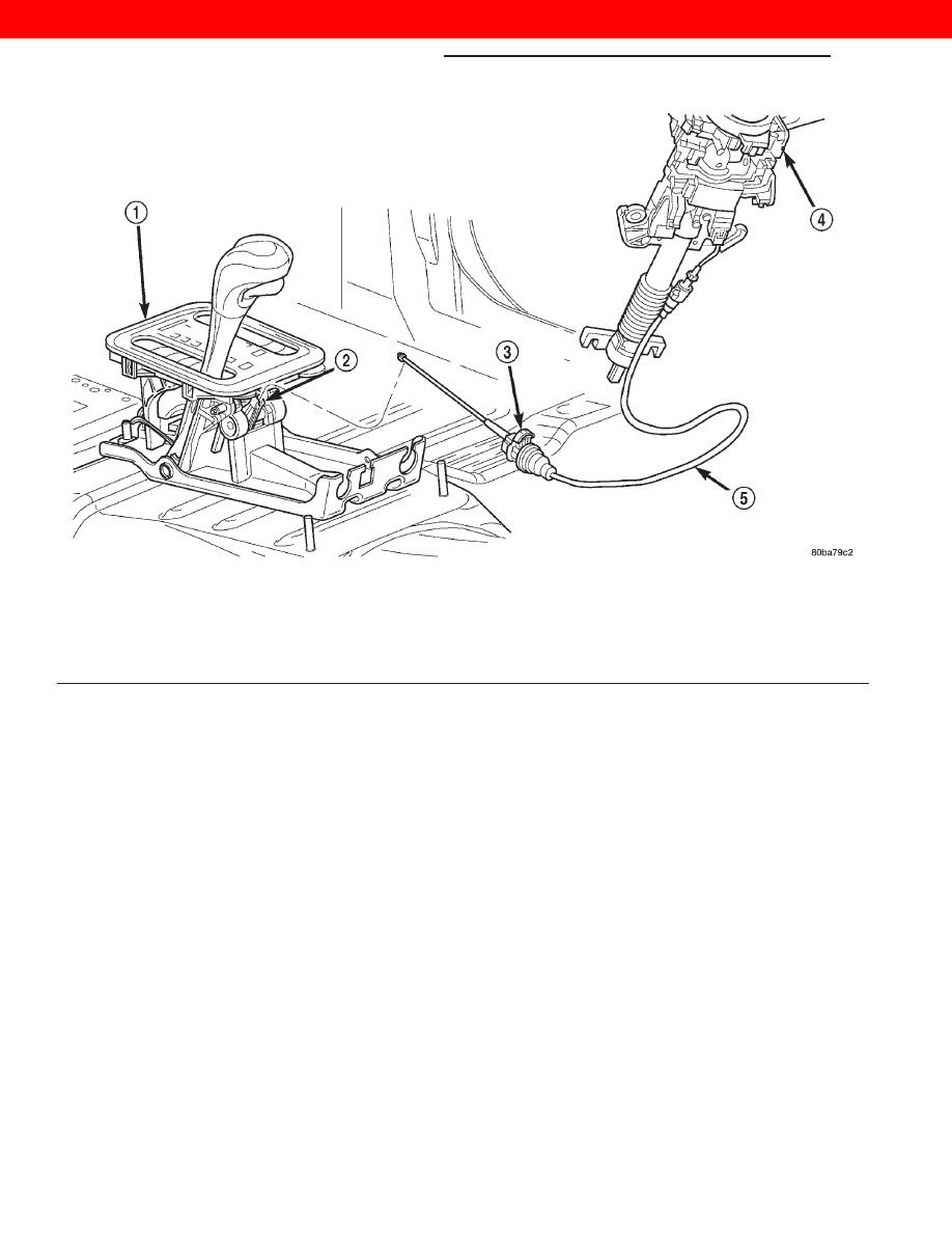
Fig. 270 Brake Transmission Shift Interlock Cable

1 – SHIFT MECHANISM
2 – SHIFTER BTSI LEVER
3 – ADJUSTMENT CLIP
4 – STEERING COLUMN ASSEMBLY
5 – INTERLOCK CABLE

21 - 118

TRANSMISSION AND TRANSFER CASE

WJ

ADJUSTMENTS (Continued)

2000 JEEP GRAND CHEROKEE

(3) Disconnect the throttle valve cable end (B)

from the throttle bell crank lever (C). Carefully
slide cable off stud. Do not pry or pull cable off.

(4) Pry the T. V. cable lock (A) into the UP position

(Fig. 274). This will unlock the cable and allow for
readjustment.

(5) Apply just enough tension on the T. V. cable (B)

to remove any slack in the braided cable. Pulling to
tight will cause the T. V. lever on the transmis-
sion to move out of its idle position, which will
result in an incorrect T. V. cable adjustment.
Slide the sheath of the T. V. cable (D) back and forth
until the centerlines of the T. V. cable end (B) and
the throttle bell crank lever (C) are aligned within
one millimeter (1mm) (Fig. 274).

(6) While holding the T. V. cable in the set position

push the T. V. cable lock (A) into the down position
(Fig. 274). This will lock the present T. V. cable
adjustment.

(7) Reconnect the T. V. cable (B) to the throttle bell

crank lever (C) (Fig. 274).

(8) Double check cable operation and adjustment.

Verify the transmission throttle valve lever and the
throttle bell crank lever move simultaneously.

(9) Install the intercooler outlet hose on the

engine.

(10) Connect the negative battery cable.

GEARSHIFT CABLE

Check adjustment by starting the engine in Park

and Neutral. Gearshift cable adjustment is COR-
RECT if the engine starts only in the Park and Neu-
tral positions. Adjustment is INCORRECT if the
engine starts in one but not both positions. If the
engine starts in any position other than Park or Neu-
tral, or if the engine will not start at all, the park/
neutral position switch or transmission range sensor
may be faulty.

Gearshift Adjustment Procedure

(1) Shift the transmission into the “Park” position.
(2) Remove the shift lever bezel and floor console

as necessary for access to the shift cable adjustment
screw (Fig. 275). Located near the shifter assembly.

(3) Loosen the shift cable adjustment screw (Fig.

275).

(4) Raise the vehicle on a hoist.
(5) Unsnap the cable eyelet from the transmission

shift lever (Fig. 276).

(6) Verify the transmission shift lever is in Park

position by moving lever fully rearward. Last rear-
ward detent is Park position (Fig. 276).

Fig. 271 Throttle Valve Cable at Transmission

1 – TRANSMISSION SHIFTER CABLE
2 – THROTTLE VALVE CABLE
3 – TRANSFER CASE SHIFTER CABLE
4 – TRANSFER CASE SHIFTER CABLE BRACKET RETAINING

BOLT (1 OF 2)

5 – THROTTLE VALVE CABLE BRACKET RETAINING BOLT
6 – ELECTRICAL CONNECTORS
7 – TRANSMISSION FLUID LINES

Fig. 272 Throttle Valve Cable at Transmission

1 – TRANSMISSION SHIFTER CABLE
2 – THROTTLE VALVE CABLE
3 – TRANSFER CASE SHIFTER CABLE
4 – TRANSFER CASE SHIFTER CABLE BRACKET RETAINING

BOLT (1 OF 2)

5 – THROTTLE VALVE CABLE BRACKET RETAINING BOLT
6 – ELECTRICAL CONNECTORS
7 – TRANSMISSION FLUID LINES

WJ

TRANSMISSION AND TRANSFER CASE

21 - 119

ADJUSTMENTS (Continued)

2000 JEEP GRAND CHEROKEE

(7) Verify positive engagement of transmission

park lock by attempting to rotate propeller shaft.
Shaft will not rotate when park lock is engaged.

(8) Snap the shift cable eyelet onto the transmis-

sion shift lever (Fig. 276).

(9) Lower the vehicle on the hoist.
(10) Tighten the shift cable adjustment screw to 7

N·m (65 in. lbs.).

(11) Verify correct cable operation. Engine should

start only in the Park and Neutral positions.

(12) Install the shifter bezel and floor console com-

ponents removed for access.

BAND ADJUSTMENTS

FRONT BAND ADJUSTMENT

The front (kickdown) band adjusting screw is

located on the left side of the transmission case
above the manual valve and throttle valve levers.

(1) Raise vehicle.
(2) Loosen band adjusting screw locknut 3-5 turns

(Fig. 277). Be certain the center adjusting screw
turns freely in case. Apply lubricant to screw threads
if necessary.

Fig. 273 Throttle Valve Cable at Throttle Linkage

1 – THROTTLE LINKAGE
2 – THROTTLE VALVE CABLE LOCKING CLIP
3 – THROTTLE VALVE CABLE

Fig. 274 Throttle Valve Cable at Throttle Linkage

1 – THROTTLE LINKAGE
2 – THROTTLE VALVE CABLE LOCKING CLIP
3 – THROTTLE VALVE CABLE

Fig. 275 Shift Cable at Shifter

1 – SHIFT LEVER PIN
2 – ADJUSTMENT SCREW
3 – SHIFT CABLE
4 – SHIFTER ASSEMBLY BRACKET

21 - 120

TRANSMISSION AND TRANSFER CASE

WJ

ADJUSTMENTS (Continued)

2000 JEEP GRAND CHEROKEE

(3) Tighten the band adjusting screw to 8 N·m (72

in. lbs.) torque with Inch Pound Torque Wrench
C-3380-A, a 3-in. extension and 5/16 socket.

CAUTION: If Adapter C-3705 is needed to reach the
adjusting screw (Fig. 278), tighten the screw to only
5 N·m (47-50 in. lbs.) torque.

44RE TRANSMISSION

• Back off front band adjusting screw 1- 7/8 turns.

• Hold the center adjusting screw in position and

torque the locknut to 41 N·m (30 ft. lbs.) torque.

(4) Lower vehicle.

REAR BAND ADJUSTMENT

The transmission oil pan must be removed for

access to the rear band adjusting screw.

(1) Raise vehicle.
(2) Remove transmission oil pan and drain fluid.
(3) Loosen band adjusting screw locknut 5-6 turns

(Fig. 279). Be sure adjusting screw turns freely in
lever.

(4) Tighten adjusting screw to 8 N·m (72 in. lbs.)

torque.

44RE TRANSMISSION

• Back off adjusting screw 4 turns.

• Hold adjusting screw in place and tighten lock-

nut to 34 N·m (25 ft. lbs.) torque.

(5) Position new gasket on oil pan and install pan

on transmission. Tighten pan bolts to 17 N·m (13 ft.
lbs.) torque.

(6) Lower vehicle and refill transmission with

Mopar

t ATF Plus 3, Type 7176 fluid.

VALVE BODY

CONTROL PRESSURE ADJUSTMENTS

There are two control pressure adjustments on the

valve body;

• Line Pressure

• Throttle Pressure
Line and throttle pressures are interdependent

because each affects shift quality and timing. As a

Fig. 276 Transmission Control Cables at

Transmission

1 – TRANSMISSION SHIFTER CABLE
2 – THROTTLE VALVE CABLE
3 – TRANSFER CASE SHIFTER CABLE
4 – TRANSFER CASE SHIFTER CABLE BRACKET RETAINING

BOLT (1 OF 2)

5 – THROTTLE VALVE CABLE BRACKET RETAINING BOLT
6 – ELECTRICAL CONNECTORS
7 – TRANSMISSION FLUID LINES

Fig. 277 Front Band Adjustment Screw Location

1 – LOCK-NUT
2 – FRONT BAND ADJUSTER

Fig. 278 Band Adjustment Adapter Tool

1 – INCH-POUND TORQUE WRENCH
2 – 5/16 SOCKET
3 – ADAPTER C-3705 (TIGHTEN ADJUSTING SCREW TO ONLY

5 N·m/50 IN-LBS IF ADAPTER IS USED)

WJ

TRANSMISSION AND TRANSFER CASE

21 - 121

ADJUSTMENTS (Continued)

2000 JEEP GRAND CHEROKEE


Content   ..  515  516  517  518   ..