Jeep Grand Cherokee WJ. Manual - part 477


  Index      Jeep     Jeep Grand Cherokee WJ - service repair manual 2001 year


Search            


Content   ..  475  476  477  478   ..


Jeep Grand Cherokee WJ. Manual - part 477


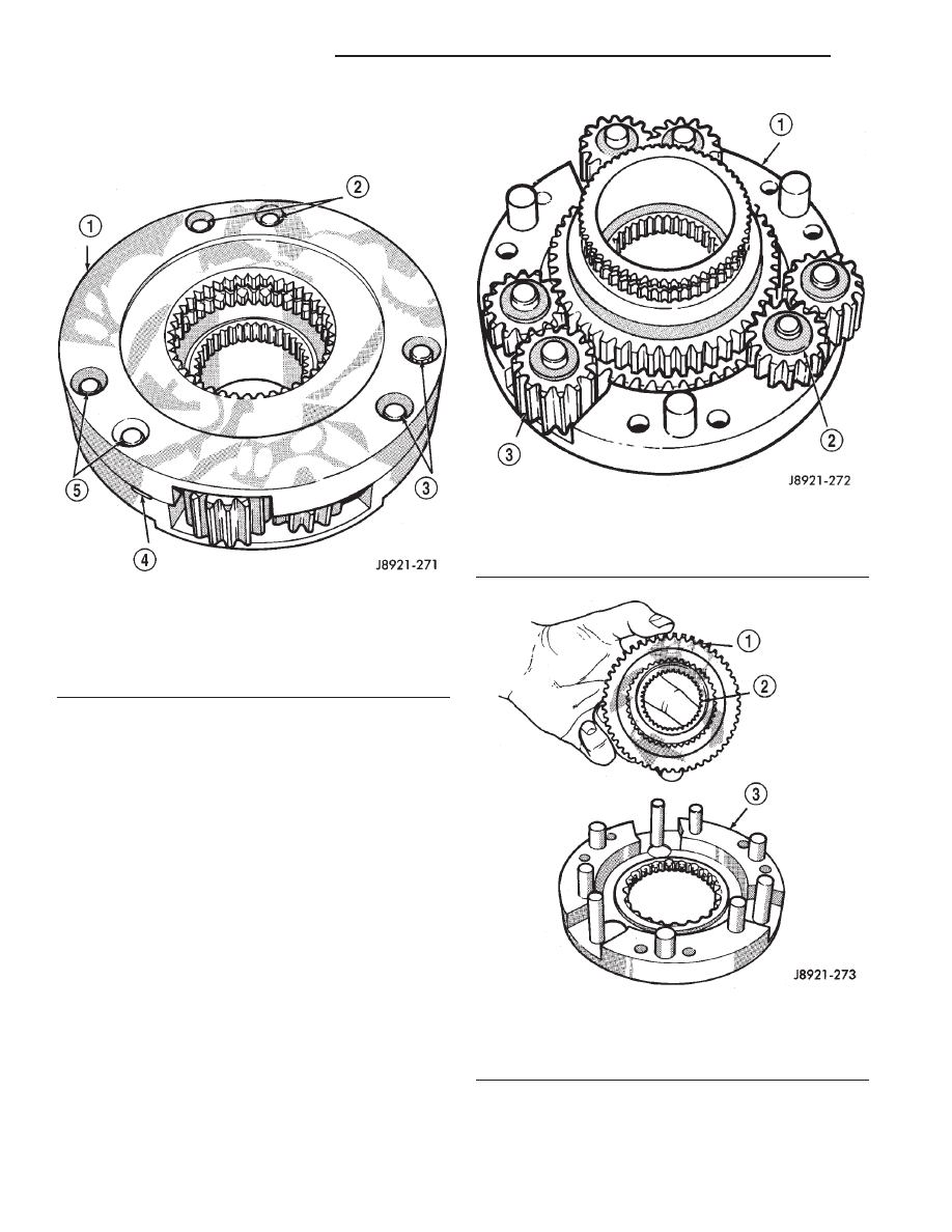
(6) Remove mainshaft and sprocket gears from

bottom case (Fig. 55). Note gear position for reference
before separating them.

ASSEMBLY

Lubricate transfer case components with automatic

transmission fluid or petroleum jelly (where indi-
cated) during assembly.

CAUTION: The bearing bores in various transfer
case components contain oil feed holes. Make sure
replacement bearings do not block the holes.

BEARING AND SEAL

(1) Remove snap-ring that retains front output

shaft front bearing in case (Fig. 56). Then remove
bearing. Use hammer handle, or hammer and brass
punch to tap bearing out of case.

Fig. 53 Separating Differential Case Halves

1 – TOP CASE
2 – CASE BOLTS
3 – CASE BOLTS
4 – CASE SLOTS
5 – CASE BOLTS

Fig. 54 Planet Gears And Thrust Washer Removal

1 – BOTTOM CASE
2 – THRUST WASHERS (12)
3 – PLANET GEARS (6)

Fig. 55 Mainshaft And Sprocket Gear Removal

1 – MAINSHAFT GEAR
2 – SPROCKET GEAR
3 – BOTTOM CASE

21 - 290

NV242 TRANSFER CASE

WJ

DISASSEMBLY AND ASSEMBLY (Continued)

(2) Install new front output shaft front bearing

with Tool Handle C-4171 and Installer 8033A with
the tapered cone upward (Fig. 57).

(3) Install front bearing snap-ring (Fig. 56).

(4) Remove front output shaft seal using an appro-

priate pry tool (Fig. 58) or slide-hammer mounted
screw.

(5) Install new front output shaft oil seal with

Installer 6952-A (Fig. 59).

(6) Remove input gear bearing with Tool Handle

C-4171 and Remover C-4210 (Fig. 60).

(7) Install snap-ring on new input gear bearing.

Fig. 56 Front Output Shaft Front Bearing Snap-Ring

Removal

1 – FRONT BEARING SNAP RING

Fig. 57 Front Output Shaft Front Bearing Installation

1 – SPECIAL TOOL C-4171
2 – SPECIAL TOOL 8033A

Fig. 58 Remove Front Output Shaft Seal

1 – OUTPUT SHAFT SEAL
2 – PRYBAR

Fig. 59 Install Front Output Shaft Seal

1 – INSTALLER 6952–A
2 – TRANSFER CASE

WJ

NV242 TRANSFER CASE

21 - 291

DISASSEMBLY AND ASSEMBLY (Continued)

(8) Install new input gear bearing with Tool Han-

dle C-4171 and Remover C-4210. Install bearing far
enough to seat snap-ring against case (Fig. 61).

(9) Remove the input gear pilot bearing by insert-

ing a suitably sized drift into the splined end of the
input gear and driving the bearing out with the drift
and a hammer (Fig. 62).

(10) Install new pilot bearing with Installer 8128

and Handle C-4171 (Fig. 63).

(11) Install new seal in front bearing retainer with

Installer 7884 (Fig. 64).

(12) Remove output shaft rear bearing with the

screw and jaws from Remover L-4454 and Cup 8148
(Fig. 65).

Fig. 60 Input Gear Bearing Removal

1 – SPECIAL TOOL C-4171
2 – SPECIAL TOOL C-4210

Fig. 61 Seating Input Gear Bearing

1 – SNAP RING
2 – INPUT SHAFT BEARING

Fig. 62 Remove Input Gear Pilot Bearing

1 – DRIFT
2 – INPUT GEAR

Fig. 63 Install Input Gear Pilot Bearing

1 – HANDLE C-4171
2 – INSTALLER 8128
3 – INPUT GEAR

21 - 292

NV242 TRANSFER CASE

WJ

DISASSEMBLY AND ASSEMBLY (Continued)

(13) Install new bearing with Tool Handle C-4171

and Installer 5066 (Fig. 66). Lubricate bearing after
installation.

(14) Install new seal in oil pump feed housing with

Special Tool 7888 (Fig. 67).

(15) Install new pickup tube O-ring in oil pump

(Fig. 68).

(16) Remove rear retainer bearing with Installer

8128 and Handle C-4171, NV242HD only.

(17) Install rear bearing in retainer with Handle

C-4171 and Installer 5064 (Fig. 69), NV242HD only.

Fig. 64 Front Bearing Retainer Seal Installation

1 – FRONT BEARING RETAINER
2 – SPECIAL TOOL 7884

Fig. 65 Remove Front Output Shaft Rear Bearing

1 – REAR CASE
2 – SPECIAL TOOL L-4454–1 AND L-4454–3
3 – SPECIAL TOOL 8148

Fig. 66 Install Front Output Shaft Rear Bearing

1 – HANDLE C-4171
2 – OUTPUT SHAFT INNER BEARING
3 – INSTALLER 5066

Fig. 67 Oil Pump Seal Installation

1 – HOUSING SEAL
2 – SPECIAL TOOL 7888
3 – OIL PUMP FEED HOUSING

WJ

NV242 TRANSFER CASE

21 - 293

DISASSEMBLY AND ASSEMBLY (Continued)


Content   ..  475  476  477  478   ..