Jeep Grand Cherokee WJ. Manual - part 457


  Index      Jeep     Jeep Grand Cherokee WJ - service repair manual 2001 year


Search            


Content   ..  455  456  457  458   ..


Jeep Grand Cherokee WJ. Manual - part 457


pressure. As the air pressure is released, the clutch
should also release.

CONVERTER HOUSING FLUID LEAK
DIAGNOSIS

When diagnosing converter housing fluid leaks,

two items must be established before repair.

(1) Verify that a leak condition actually exists.
(2) Determined the true source of the leak.
Some suspected converter housing fluid leaks may

not be leaks at all. They may only be the result of
residual fluid in the converter housing, or excess
fluid spilled during factory fill or fill after repair.
Converter

housing

leaks

have

several

potential

sources. Through careful observation, a leak source
can be identified before removing the transmission
for repair. Pump seal leaks tend to move along the
drive hub and onto the rear of the converter. Pump
cover O-ring leaks follow the same path as a seal
leak.

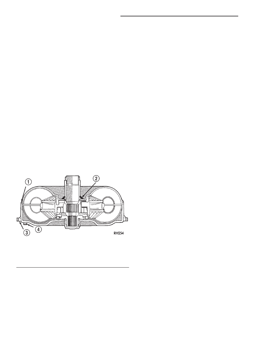
TORQUE CONVERTER LEAK POINTS

Possible sources of converter leaks are:
(1) Leaks at the weld joint around the outside

diameter weld (Fig. 36).

(2) Leaks at the converter hub weld (Fig. 36).

SERVICE PROCEDURES

FLUID LEVEL CHECK

Low fluid level can cause a variety of conditions

because it allows the pump to take in air along with
the fluid. As in any hydraulic system, air bubbles
make the fluid spongy, therefore, pressures will be
low and build up slowly.

Improper filling can also raise the fluid level too

high. When the transmssion has too much fluid, the

geartrain churns up foam and cause the same condi-
tions which occur with a low fluid level.

In either case, air bubbles can cause overheating

and/or fluid oxidation, and varnishing. This can
interfere with normal valve, clutch, and accumulator
operation. Foaming can also result in fluid escaping
from the transmission vent where it may be mis-
taken for a leak.

Along with fluid level, it is important to check the

condition of the fluid. When the fluid smells burned,
and is contaminated with metal or friction material
particles, a complete transmission recondition is
needed. Be sure to examine the fluid on the dipstick
closely. If there is any doubt about its condition,
drain out a sample for a double check.

After the fluid has been checked, seat the dipstick

fully to seal out water and dirt.

The transmission fluid level should be inspected at

least every six months.

FLUID LEVEL CHECK PROCEDURE

The transmission has a dipstick to check oil level.

It is located on the right side of the engine. Be sure
to wipe all dirt from dipstick handle before removing.

The torque converter fills in both the P Park and N

Neutral positions. Place the selector lever in P Park
to be sure that the fluid level check is accurate. The
engine should be running at idle speed for at
least one minute, with the vehicle on level
ground. 
At normal operating temperature (approxi-
mately 82° C or 180° F), the fluid level is correct if it
is in the HOT region (cross-hatched area) on the oil
level indicator. The fluid level will be approximately
at the upper COLD hole of the dipstick at 70° F fluid
temperature.

NOTE: Engine and Transmission should be at nor-
mal operating temperature before performing this
procedure.

(1) Start engine and apply parking brake.
(2) Shift the transmission into Drive for approxi-

mately 2 seconds.

(3) Shift the transmission into Reverse for approx-

imately 2 seconds.

(4) Shift the transmission into Park.
(5) Hook up DRB III scan tool and select transmis-

sion.

(6) Select sensors.
(7) Read the transmission temperature value.
(8) Compare the fluid temperature value with the

chart.

(9) Adjust transmission fluid level shown on the

dipstick according to the chart.

Fig. 36 Converter Leak Points—Typical

1 – OUTSIDE DIAMETER WELD
2 – TORQUE CONVERTER HUB WELD
3 – STARTER RING GEAR
4 – LUG

21 - 210

45RFE AUTOMATIC TRANSMISSION

WJ

DIAGNOSIS AND TESTING (Continued)

NOTE: After adding any fluid to the transmission,
wait a minimum of 2 minutes for the oil to fully
drain from the fill tube into the transmission before
rechecking the fluid level.

(10) Check transmission for leaks.

FLUID AND FILTER REPLACEMENT

Refer to the Maintenance Schedules in Group 0,

Lubrication and Maintenance, for proper service
intervals. The fluid capacity of the 45RFE is approx-
imately 13.25 liters (14.0 quarts).

REMOVAL

(1) Hoist and support vehicle on safety stands.
(2) Place a large diameter shallow drain pan

beneath the transmission pan.

(3) Remove bolts holding front and sides of pan to

transmission.

(4) Loosen bolts holding rear of pan to transmis-

sion.

(5) Slowly separate front of pan away from trans-

mission allowing the fluid to drain into drain pan.

(6) Hold up pan and remove remaining bolt hold-

ing pan to transmission.

(7) While holding pan level, lower pan away from

transmission.

(8) Pour remaining fluid in pan into drain pan.

(9) Remove screws holding filter to valve body

(Fig. 37).

(10) Separate filter from valve body and oil pump

and pour fluid in filter into drain pan.

(11) Remove and discard the oil filter seal from the

bottom of the oil pump.

(12) Using Oil Filter Wrench 8321, remove the

cooler return filter from the transmission.

(13) Dispose of used trans fluid and filter properly.

Transmission Fluid Temperature Chart

Fig. 37 Transmission Filters

WJ

45RFE AUTOMATIC TRANSMISSION

21 - 211

SERVICE PROCEDURES (Continued)

INSPECTION

Inspect bottom of pan and magnet for excessive

amounts of metal. A light coating of clutch material
on the bottom of the pan does not indicate a problem
unless accompanied by a slipping condition or shift
lag. If fluid and pan are contaminated with excessive
amounts or debris, refer to the diagnosis section of
this group.

CLEANING

(1) Using a suitable solvent, clean pan and mag-

net.

(2) Using a suitable gasket scraper, clean original

sealing material from surface of transmission case
and the transmission pan.

INSTALLATION

(1) Install a new oil filter seal into the bottom of

the oi pump.

NOTE: Do not attempt to install the seal onto the
oil filter first and then into the oil pump. An unsat-
isfactory seal between the oil pump and filter will
result, allowing air to be drawn into the pump.

(2) Place replacement filter in position on valve

body and into the oil pump.

(3) Install screws to hold filter to valve body (Fig.

37). Tighten screws to 4.5 N·m (40 in. lbs.) torque.

(4) Install new cooler return filter onto the trans-

mission. Torque the filter to 14.12 N·m (125 in. lbs.).

(5) Place bead of Mopar

t RTV sealant onto the

transmission case sealing surface.

(6) Place pan in position on transmission.
(7) Install screws to hold pan to transmission.

Tighten bolts to 11.8 N·m (105 in. lbs.) torque.

(8) Lower

vehicle

and

fill

transmission

with

Mopar

t ATF Plus 3, type 7176 fluid.

TRANSMISSION FILL PROCEDURE

To avoid overfilling transmission after a fluid

change or overhaul, perform the following procedure:

(1) Remove dipstick and insert clean funnel in

transmission fill tube.

(2) Add following initial quantity of Mopar

t ATF

Plus 3 to transmission:

(a) If only fluid and filter were changed, add 10

pints (5 quarts) of ATF Plus 3 to transmission.

(b) If transmission was completely overhauled,

torque converter was replaced or drained, and
cooler was flushed, add 24 pints (12 quarts) of
ATF Plus 3 to transmission.
(3) Refer to the Fluid Level Check information in

this group for the proper fill procedures.

OIL PUMP VOLUME CHECK

Measuring the oil pump output volume will deter-

mine if sufficient oil flow to the transmission oil
cooler exists, and whether or not an internal trans-
mission failure is present.

Verify that the transmission fluid is at the proper

level. Refer to the Fluid Level Check procedure in
this section. If necessary, fill the transmission to the
proper level with Mopar

t ATF+3, type 7176, Auto-

matic Transmission Fluid.

(1) Disconnect the To cooler line at the cooler

inlet and place a collecting container under the dis-
connected line.

CAUTION: With the fluid set at the proper level,
fluid collection should not exceed (1) quart or inter-
nal damage to the transmission may occur.

(2) Run the engine at curb idle speed, with the

shift selector in neutral.

(3) If one quart of transmission fluid is collected in

the container in 20 seconds or less, oil pump flow vol-
ume is within acceptable limits. If fluid flow is inter-
mittent, or it takes more than 20 seconds to collect
one quart of fluid, refer to the Hydraulic Pressure
tests in this section for further diagnosis.

(4) Re-connect the To cooler line to the transmis-

sion cooler inlet.

(5) Refill the transmission to proper level.

FLUSHING COOLERS AND TUBES

When a transmission failure has contaminated the

fluid, the oil cooler(s) must be flushed. The torque
converter must also be replaced. This will insure that
metal particles or sludged oil are not later trans-
ferred back into the reconditioned (or replaced) trans-
mission.

The only recommended procedure for flushing cool-

ers and lines is to use Tool 6906A Cooler Flusher.

WARNING: WEAR PROTECTIVE EYEWEAR THAT
MEETS THE REQUIREMENTS OF OSHA AND ANSI
Z87.1–1968. WEAR STANDARD INDUSTRIAL RUB-
BER GLOVES.

KEEP LIGHTED CIGARETTES, SPARKS, FLAMES,

AND OTHER IGNITION SOURCES AWAY FROM THE
AREA TO PREVENT THE IGNITION OF COMBUSTI-
BLE LIQUIDS AND GASES. KEEP A CLASS (B) FIRE
EXTINGUISHER

IN

THE

AREA

WHERE

THE

FLUSHER WILL BE USED.

KEEP THE AREA WELL VENTILATED.
DO NOT LET FLUSHING SOLVENT COME IN CON-

TACT WITH YOUR EYES OR SKIN: IF EYE CONTAM-
INATION OCCURS, FLUSH EYES WITH WATER FOR
15 TO 20 SECONDS. REMOVE CONTAMINATED
CLOTHING AND WASH AFFECTED SKIN WITH
SOAP AND WATER. SEEK MEDICAL ATTENTION.

21 - 212

45RFE AUTOMATIC TRANSMISSION

WJ

SERVICE PROCEDURES (Continued)

COOLER FLUSH USING TOOL 6906A

(1) Remove cover plate filler plug on Tool 6906A.

Fill reservoir 1/2 to 3/4 full of fresh flushing solution.
Flushing solvents are petroleum based solutions gen-
erally used to clean automatic transmission compo-
nents. DO NOT use solvents containing acids, water,
gasoline, or any other corrosive liquids.

(2) Reinstall filler plug on Tool 6906A.
(3) Verify pump power switch is turned OFF. Con-

nect red alligator clip to positive (+) battery post.
Connect black (-) alligator clip to a good ground.

(4) Disconnect the cooler lines at the transmission.

NOTE: When

flushing

transmission

cooler

and

lines, ALWAYS reverse flush.

(5) Connect the BLUE pressure line to the OUT-

LET (From) cooler line.

(6) Connect the CLEAR return line to the INLET

(To) cooler line

(7) Turn pump ON for two to three minutes to

flush cooler(s) and lines.

(8) Turn pump OFF.
(9) Disconnect CLEAR suction line from reservoir

at cover plate. Disconnect CLEAR return line at
cover plate, and place it in a drain pan.

(10) Turn pump ON for 30 seconds to purge flush-

ing solution from cooler and lines. Turn pump OFF.

(11) Place CLEAR suction line into a one quart

container of Mopar

t ATF Plus 3, type 7176 automatic

transmission fluid.

(12) Turn pump ON until all transmission fluid is

removed from the one quart container and lines. This
purges any residual cleaning solvent from the trans-
mission cooler and lines. Turn pump OFF.

(13) Disconnect alligator clips from battery. Recon-

nect flusher lines to cover plate, and remove flushing
adapters from cooler lines.

TRANSMISSION QUICK LEARN PROCEDURE

The quick learn procedure requires the use of the

DRB scan tool.

This program allows the electronic transmission

system to recalibrate itself. This will provide the best
possible transmission operation. The quick learn pro-
cedure should be performed if any of the following
procedures are performed:

• Transmission Assembly Replacement

• Transmission Control Module Replacement

• Solenoid Pack Replacement

• Clutch Plate and/or Seal Replacement

• Valve Body Replacement or Recondition
To perform the Quick Learn Procedure, the follow-

ing conditions must be met:

• The brakes must be applied

• The engine speed must be above 500 rpm

• The throttle angle (TPS) must be less than 3

degrees

• The shift lever position must stay until

prompted to shift to overdrive

• The shift lever position must stay in overdrive

after the Shift to Overdrive prompt until the DRB
indicates the procedure is complete

• The calculated oil temperature must be above

60° and below 200°

ALUMINUM THREAD REPAIR

Damaged or worn threads in the aluminum trans-

mission case and valve body can be repaired by the
use of Heli-Coils, or equivalent. This repair consists
of drilling out the worn-out damaged threads. Then
tap the hole with a special Heli-Coil tap, or equiva-
lent, and installing a Heli-Coil insert, or equivalent,
into the hole. This brings the hole back to its original
thread size.

Heli-Coil, or equivalent, tools and inserts are readily

available from most automotive parts suppliers.

REMOVAL AND INSTALLATION

INPUT SPEED SENSOR

REMOVAL

(1) Raise vehicle.
(2) Place a suitable fluid catch pan under the

transmission.

(3) Remove the wiring connector from the input

speed sensor (Fig. 38).

(4) Remove the bolt holding the input speed sensor

to the transmission case.

(5) Remove the input speed sensor from the trans-

mission case.

Fig. 38 Input Speed Sensor

WJ

45RFE AUTOMATIC TRANSMISSION

21 - 213

SERVICE PROCEDURES (Continued)


Content   ..  455  456  457  458   ..