Jeep Grand Cherokee WJ. Manual - part 425


  Index      Jeep     Jeep Grand Cherokee WJ - service repair manual 2001 year


Search            


Content   ..  423  424  425  426   ..


Jeep Grand Cherokee WJ. Manual - part 425


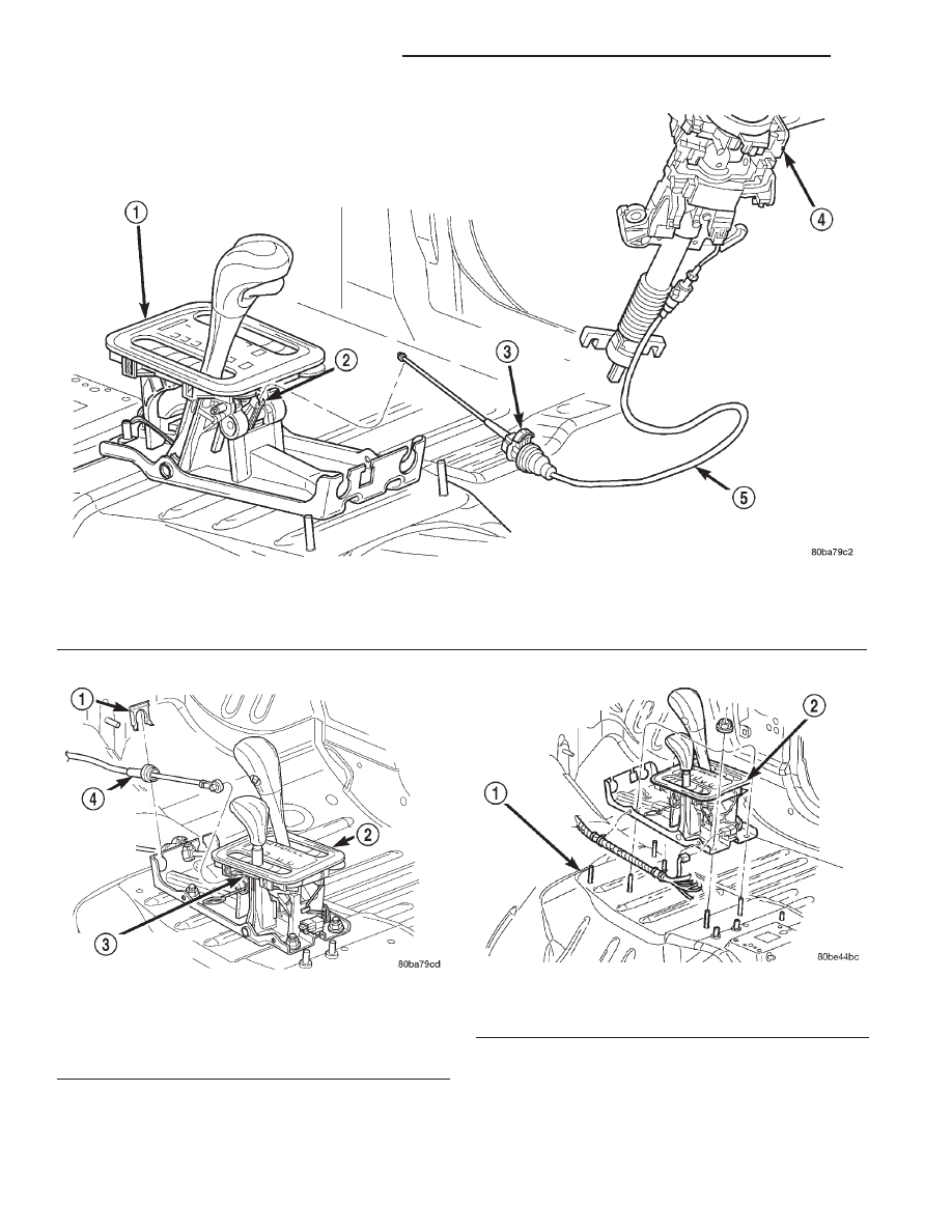
Fig. 89 Brake Transmission Interlock Cable

1 – SHIFT MECHANISM
2 – SHIFTER BTSI LEVER
3 – ADJUSTMENT CLIP

4 – STEERING COLUMN ASSEMBLY
5 – INTERLOCK CABLE

Fig. 90 Transfer Case Shift Cable

1 – CLIP
2 – SHIFTER
3 – TRANSFER CASE SHIFT LEVER PIN
4 – TRANSFER CASE SHIFT CABLE

Fig. 91 Shifter Assembly

1 – FLOOR PAN
2 – SHIFTER ASSEMBLY

21 - 82

42RE AUTOMATIC TRANSMISSION

WJ

REMOVAL AND INSTALLATION (Continued)

BRAKE TRANSMISSION SHIFT INTERLOCK

REMOVAL

(1) Lower the steering column.
(2) Remove the transmission shift interlock cable

from steering column (Fig. 92).

(3) Remove the center console and related trim.

Refer to Group 23, Body, for proper procedures.

(4) Disconnect the BTSI cable from the shift BTSI

lever and remove the cable from the shifter assembly
bracket.

(5) Disengage the wire connector at the solenoid

on the cable

(6) Release the BTSI cable from any remaining

clips.

(7) Remove BTSI cable from the vehicle.

INSTALLATION

NOTE: The gearshift cable must be secured into
position and properly adjusted before the installa-
tion of the Brake Transmission Interlock Cable
(BTSI).

(1) Snap the BTSI cable assembly into the steering

column.

(2) Snap BTSI cable solenoid tie strap into hole in

steering column tube.

(3) Engage the wiring connector from brake light

switch into BTSI cable solenoid housing.

(4) Route BTSI cable to the shifter mechanism.
(5) Install the BTSI cable end fitting into shifter

BTSI lever.

(6) Pull rearward on the BTSI cable housing and

install the cable housing into the shifter assembly
bracket.

(7) Place the ignition key cylinder in the LOCK

position.

(8) Snap BTSI cable adjuster ears into floor shifter

bracket and

(9) Push the cable adjuster lock clamp downward

to lock it.

(10) Install the center console and related trim.

Refer to Group 23, Body, for proper procedures.

(11) Test the BTSI cable operation.

Fig. 92 Brake Transmission Shift Interlock

1 – SHIFT MECHANISM
2 – SHIFTER BTSI LEVER
3 – ADJUSTMENT CLIP

4 – STEERING COLUMN ASSEMBLY
5 – INTERLOCK CABLE

WJ

42RE AUTOMATIC TRANSMISSION

21 - 83

REMOVAL AND INSTALLATION (Continued)

GOVERNOR SOLENOID AND PRESSURE
SENSOR

REMOVAL

(1) Hoist and support vehicle on safety stands.
(2) Remove transmission fluid pan and filter.
(3) Disengage wire connectors from pressure sen-

sor and solenoid (Fig. 93).

(4) Remove

screws

holding

pressure

solenoid

retainer to governor body.

(5) Separate solenoid retainer from governor (Fig.

94).

(6) Pull solenoid from governor body (Fig. 95).
(7) Pull pressure sensor from governor body.
(8) Remove bolts holding governor body to valve

body.

(9) Separate governor body from valve body (Fig.

96).

(10) Remove governor body gasket.

INSTALLATION

Before installing the pressure sensor and solenoid

in the governor body, replace O-ring seals, clean the
gasket surfaces and replace gasket.

(1) Place gasket in position on back of governor

body (Fig. 96).

(2) Place governor body in position on valve body.
(3) Install bolts to hold governor body to valve

body.

(4) Lubricate

O-ring

on

pressure

sensor

with

transmission fluid.

(5) Align pressure sensor to bore in governor body.
(6) Push pressure sensor into governor body.
(7) Lubricate O-ring, on pressure solenoid, with

transmission fluid.

(8) Align pressure solenoid to bore in governor

body (Fig. 95).

(9) Push solenoid into governor body.
(10) Place solenoid retainer in position on governor

(Fig. 94).

(11) Install

screws

to

hold

pressure

solenoid

retainer to governor body.

(12) Engage wire connectors into pressure sensor

and solenoid (Fig. 93).

(13) Install transmission fluid pan and (new) filter.
(14) Lower vehicle and road test to verify repair.

VALVE BODY

The valve body can be removed for service without

having to remove the transmission assembly.

The valve body can be disassembled for cleaning

and inspection of the individual components. Refer to
Disassembly and Assembly section for proper proce-
dures.

The only replaceable valve body components are:
• Manual lever.

• Manual lever washer, seal, E-clip, and shaft

seal.

• Manual lever detent ball.

• Throttle lever.

• Fluid filter.

• Pressure adjusting screw bracket.

• Governor pressure solenoid.

• Governor pressure sensor (includes transmission

temperature thermistor).

• Converter clutch/overdrive solenoid assembly

and harness.

• Governor housing gasket.

• Solenoid case connector O-rings.
The remaining valve body components are serviced

only as part of a complete valve body assembly.

Fig. 93 Governor Solenoid And Pressure Sensor

1 – PRESSURE SENSOR
2 – PRESSURE SOLENOID
3 – GOVERNOR

Fig. 94 Pressure Solenoid Retainer

1 – PRESSURE SOLENOID RETAINER
2 – GOVERNOR

21 - 84

42RE AUTOMATIC TRANSMISSION

WJ

REMOVAL AND INSTALLATION (Continued)

REMOVAL

(1) Shift transmission into NEUTRAL.
(2) Raise vehicle.
(3) Remove gearshift and throttle levers from shaft

of valve body manual lever.

(4) Disconnect wires at solenoid case connector

(Fig. 97).

(5) Position drain pan under transmission oil pan.
(6) Remove transmission oil pan and gasket.
(7) Remove fluid filter from valve body.
(8) Remove bolts attaching valve body to transmis-

sion case.

(9) Lower valve body enough to remove accumula-

tor piston and springs.

(10) Work manual lever shaft and electrical con-

nector out of transmission case.

(11) Lower valve body, rotate valve body away

from case, pull park rod out of sprag, and remove
valve body (Fig. 98).

INSTALLATION

(1) Check condition of O-ring seals on valve body

harness connector (Fig. 99). Replace seals on connec-
tor body if cut or worn.

Fig. 95 Pressure Solenoid and O-ring

1 – PRESSURE SOLENOID
2 – O-RING
3 – GOVERNOR

Fig. 96 Governor Body and Gasket

1 – GOVERNOR BODY
2 – GASKET

Fig. 97 Transmission Case Connector

1 – SOLENOID CASE CONNECTOR
2 – PARK/NEUTRAL POSITION SWITCH CONNECTOR

TERMINAL

Fig. 98 Valve Body

1 – VALVE BODY
2 – WIRE HARNESS
3 – PARK ROD
4 – GOVERNOR PRESSURE SOLENOID
5 – GOVERNOR PRESSURE SENSOR

WJ

42RE AUTOMATIC TRANSMISSION

21 - 85

REMOVAL AND INSTALLATION (Continued)


Content   ..  423  424  425  426   ..