Jeep Grand Cherokee WJ. Manual - part 317
(43) Fill
crankcase
with
engine
oil.
Refer
to
LUBRICATION and MAINTENANCE for correct
capacities.
(44) Fill the cooling system with reusable coolant
or new coolant Refer to COOLING SYSTEM.
(45) Align the hood to the scribe marks. Install the
hood.
(46) Install the air cleaner assembly.
(47) Install the battery and connect the battery
cable.
WARNING: USE EXTREME CAUTION WHEN THE
ENGINE IS OPERATING. DO NOT STAND IN A
DIRECT LINE WITH THE FAN. DO NOT PUT YOUR
HANDS NEAR THE PULLEYS, BELTS OR FAN. DO
NOT WEAR LOOSE CLOTHING.
(48) Start the engine, inspect for leaks and correct
the fluid levels, as necessary.
INTAKE AND EXHAUST MANIFOLD
REMOVAL
NOTE: THE ENGINE INTAKE AND EXHAUST MANI-
FOLD
MUST
BE
REMOVED
AND
INSTALLED
TOGETHER. THE MANIFOLDS USE A COMMON
GASKET AT THE CYLINDER HEAD.
(1) Disconnect the battery negative cable.
(2) Remove air cleaner inlet hose from throttle
body assembly.
(3) Remove the air cleaner assembly.
(4) Remove the throttle cable, vehicle speed control
cable (if equipped) and the transmission line pres-
sure cable.
(5) Disconnect the following electrical connections
and secure their harness out of the way:
• Throttle Position Sensor
• Idle Air Control Motor
• Coolant Temperature Sensor (at thermostat
housing)
• Intake Air Temperature Sensor
• Oxygen Sensor
• Crank Position Sensor
• Six (6) Fuel Injector Connectors
(6) Disconnect the Map Sensor, HVAC, and Brake
Booster vacuum supply hoses at the intake manifold.
(7) Perform the fuel pressure release procedure.
(Refer to Group 14, Fuel Systems for correct proce-
dure)
(8) Disconnect and remove the fuel system supply
line from the fuel rail assembly. (Refer to Group 14,
Quick Connect Fittings for correct procedures)
(9) Remove the accessory drive belt (refer to Group
7, Cooling System). Loosen the tensioner.
(10) Remove the power steering pump and bracket
from the intake manifold and set aside.
(11) Raise the vehicle.
(12) Disconnect the exhaust pipes from the engine
exhaust manifolds.
(13) Lower the vehicle.
(14) Remove
the
intake
manifold
and
engine
exhaust manifolds.
INSTALLATION
If the manifold is being replaced, ensure all the fit-
ting, etc. are transferred to the replacement mani-
fold.
(1) Install a new engine exhaust/intake manifold
gasket over the alignment dowels on the cylinder
head.
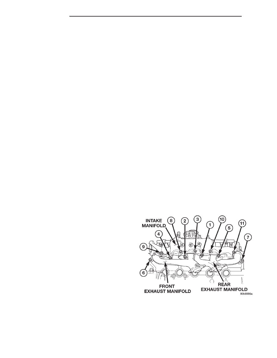
(2) Position the engine exhaust manifolds to the
cylinder head. Install fastener Number 3 and finger
tighten at this time (Fig. 47).
(3) Install intake manifold on the cylinder head
dowels.
(4) Install washer and fastener Numbers 1, 2, 4, 5,
8, 9, 10 and 11 (Fig. 47).
(5) Install washer and fastener Numbers 6 and 7
(Fig. 47).
(6) Tighten the fasteners in sequence and to the
specified torque (Fig. 47).
• Fastener Numbers 1 through 5—Tighten to 33
N·m (24 ft. lbs.) torque.
• Fastener Numbers 6 and 7—Tighten to 14 N·m
(126 in. lbs.) torque.
• Fastener Numbers 8 through 11—Tighten to 33
N·m (24 ft. lbs.) torque.
(7) Install the power steering pump and bracket to
the intake manifold. Tighten the belt to specification.
(Refer to Group 7, Cooling System for the correct pro-
cedures)
(8) Install the fuel system supply line to the fuel
rail assembly. Before connecting the fuel supply
Fig. 47 Intake and Exhaust Manifolds—4.0L
9 - 34
4.0L ENGINE
WJ
REMOVAL AND INSTALLATION (Continued)