Jeep Grand Cherokee WJ. Manual - part 316


  Index      Jeep     Jeep Grand Cherokee WJ - service repair manual 2001 year


Search            


Content   ..  314  315  316  317   ..


Jeep Grand Cherokee WJ. Manual - part 316


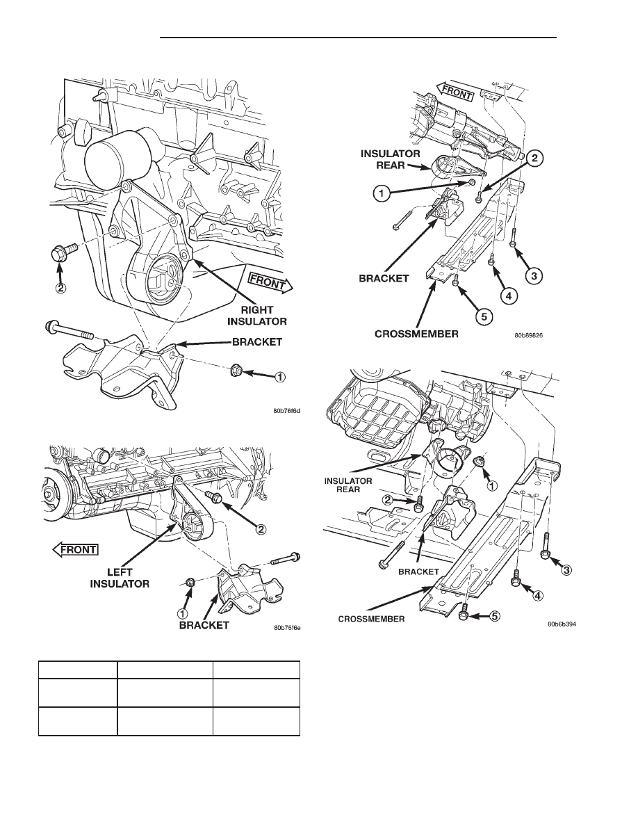
Fig. 40 Front Engine Mount—Right Side

Fig. 41 Front Engine Mount—Left Side

ITEM

DESCRIPTION

TORQUE

1

NUT

(Qty 1 Per side)

61N·m

(45 ft. lbs.)

2

Bolt

(Qty 4 Per Side)

Fig. 42 Rear Engine Mount—(4X2)

Fig. 43 Rear Engine Mount—(4X4)

9 - 30

4.0L ENGINE

WJ

REMOVAL AND INSTALLATION (Continued)

(4) Remove the transmission support.
(5) Install the mount fastening bolts and tighten to

54 N·m (40 ft. lbs.) torque.

(6) Tighten the through bolt nut to 50 N·m (37 ft.

lbs.).

(7) Lower the vehicle.
(8) Connect the negative cable to the battery.

ENGINE BENDING BRACES

REMOVAL

The engine bending braces are used to add

strength to the powertrain and to address some
minor NVH concerns.

NOTE: Before the engine or the transmission can
be removed the engine bending braces must be
removed.

(1) Raise and support vehicle.

NOTE: Both left and right side bending braces are
removed the sameway. Only the right side is
shown.

NOTE: The exhaust does not require removal to
preform this procedure.

(2) Remove the exhaust hanger bracket retaining

bolt.

(3) Remove

locknut

and

transmission

bending

brace bar.

(4) Remove engine-to-bending brace retaining bolt,

bending brace bar and cross bar.

INSTALLATION

NOTE: DO NOT tighten the retaining hardware until
all bending braces are in place.

(1) Position the cross brace into the engine-to-

transmission brace, then position the engine-to-trans-
mission brace and install retaining bolt.

(2) Position the transmission bending brace onto

through brace and install new locknut.

(3) Position

exhaust

hanger

and

transmission

brace, install retaining bolt (Fig. 45).

(4) Tighten engine-to-transmission brace retaining

bolt (Fig. 44) to 40 N·m (30 ft. lbs.).

(5) Tighten transmission brace retaining bolts (Fig.

45) to 40 N·m (30 ft. lbs.), then tighten transmission
brace retaining lock nuts (Fig. 45) to 108 N·m (80 ft.
lbs.).

ENGINE ASSEMBLY

REMOVAL

(1) Disconnect the battery negative cable.
(2) Mark the hinge locations on the hood panel for

alignment reference during installation. Remove the
engine compartment lamp. Remove the hood.

(3) Remove the radiator drain cock and radiator

cap to drain the coolant. DO NOT waste usable cool-
ant. If the solution is clean, drain the coolant into a
clean container for reuse.

(4) Remove the upper radiator hose and coolant

recovery hose.

(5) Remove the lower radiator hose.
(6) Remove upper radiator support retaining bolts

and remove radiator support.

(7) Remove the fan assembly from the water

pump. Refer to ENGINE COOLING.

ITEM

DESCRIPTON

TORQUE

1

NUT (Qty 1)

45 N·m

(33 ft. lbs.)

2

BOLT (Qty 4)

46 N·m

(34 ft. lbs.)

3

BOLT (Qty 2

Per Side)

68 N·m

(50 ft. lbs.)

4

BOLT (Qty 2

Per Side)

46 N·m

(34 ft. lbs.)

5

BOLT (Qty 4)

46 N·m

(34 ft. lbs.)

Fig. 44 Engine-to-Transmission Bending Braces

1 – ENGINE-TO-TRANSMISSION BENDING BRACE
2 – CROSS BRACE
3 – ENGINE-TO-TRANSMISSION BENDING BRACE RETAINING

BOLT

WJ

4.0L ENGINE

9 - 31

REMOVAL AND INSTALLATION (Continued)

(8) Remove the fan shroud. Refer to ENGINE

COOLING.

(9) Disconnect the transmission fluid cooler lines

(automatic transmission).

(10) Discharge the A/C system. Refer to HEATING

and AIR CONDITIONING.

(11) Remove the service valves and cap the com-

pressor ports.

(12) Remove the radiator or radiator/condenser (if

equipped with A/C).

(13) Disconnect the heater hoses at the engine

thermostat housing and water pump.

(14) Disconnect the accelerator cable, transmission

line pressure cable and speed control cable (if
equipped) from the throttle body.

(15) Remove cables from the bracket and secure

out of the way.

(16) Disconnect the body ground at the engine.
(17) Disconnect

the

following

connectors

and

secure their harness out of the way.

• Power steering pressure switch

• Coolant temperature sensor

• Six (6) fuel injector connectors

• Intake air temperature sensor

• Throttle position sensor

• Map sensor

• Crankshaft position sensor

• Oxygen sensor

• Camshaft position sensor

• Generator connector and B+ terminal wire
(18) Disconnect the coil rail electrical connections

and the oil pressure switch connector.

(19) Perform the fuel pressure release procedure.

Refer to FUEL SYSTEM for correct procedure.

(20) Disconnect the fuel supply line at the injector

rail. (Refer to QUICK-CONNECT FITTINGS for the
correct procedure.

(21) Remove the fuel line bracket from the intake

manifold.

(22) Remove the air cleaner assembly (Fig. 46).
(23) Disconnect the hoses from the fittings at the

steering gear.

(24) Drain the pump reservoir.
(25) Cap the fittings on the hoses and steering

gear to prevent foreign objects from entering the sys-
tem.

(26) Raise and support the vehicle.
(27) Disconnect the wires from the engine starter

motor solenoid.

(28) Remove the engine starter motor.
(29) Disconnect

the

oxygen

sensor

from

the

exhaust pipe.

(30) Disconnect the exhaust pipe from the mani-

fold.

(31) Remove the exhaust pipe support.
(32) Remove the bending brace. Refer to Engine

Bending Brace in this section for procedure.

Fig. 45 Transmission Bending Braces and Exhaust

Hanger

1 – TRANSMISSION BENDING BRACE RETAINING BOLT
2 – ENGINE-TO-TRANSMISSION BENDING BRACE
3 – LOCKNUT
4 – TRANSMISSION BRACE
5 – EXHAUST HANGER

Fig. 46 Air Cleaner Assembly & Power Steering

Pump

1 – POWER STEERING PUMP
2 – AIR CLEANER ASSEMBLY

9 - 32

4.0L ENGINE

WJ

REMOVAL AND INSTALLATION (Continued)

(33) Remove the engine flywheel/converter housing

access cover.

(34) Mark the converter and drive plate location.
(35) Remove the converter-to-drive plate bolts.
(36) Remove the upper engine flywheel/converter

housing bolts and loosen the bottom bolts.

(37) Remove the engine mount cushion-to-engine

compartment bracket bolts.

(38) Lower the vehicle.
(39) Attach a lifting device to the engine.
(40) Raise the engine off the front supports.
(41) Place a support or floor jack under the con-

verter (or engine flywheel) housing.

(42) Remove the remaining converter (or engine

flywheel) housing bolts.

(43) Lift the engine out of the engine compart-

ment.

INSTALLATION

CAUTION: When installing the engine into a vehicle
equipped with an automatic transmission, be care-
ful not to damage the trigger wheel on the engine
flywheel.

(1) Attach a lifting device to the engine and lower

the engine into the engine compartment. For easier
installation, it may be necessary to remove the
engine mount bracket as an aid in alignment of the
engine to the transmission.

(2) Align the transmission torque converter hous-

ing with the engine.

(3) Loosely install the converter housing lower

bolts and install the next higher bolt and nut on each
side.

(4) Tighten all 4 bolts finger tight.
(5) Install the engine mount brackets (if removed).
(6) Lower the engine and engine mount brackets

onto the engine compartment cushions. Install the
bolts and finger tighten the nuts.

(7) Remove the engine lifting device.
(8) Raise and support the vehicle.
(9) Install the remaining engine flywheel/converter

housing bolts. Tighten all bolts to 38 N·m (28 ft. lbs.)
torque.

(10) Install the converter-to-drive plate bolts.
(11) Ensure the installation reference marks are

aligned.

(12) Install the engine flywheel/converter housing

access cover.

(13) Install the exhaust pipe support and tighten

the screw.

(14) Install the engine bending brace.
(15) Tighten the engine mount-to-bracket bolts.
(16) Connect the vehicle speed sensor wire connec-

tions and tighten the screws.

(17) Connect the exhaust pipe to the manifold.

(18) Install the engine starter motor and connect

the cable.

(19) Connect the wires to the engine starter motor

solenoid.

(20) Lower the vehicle.
(21) Connect all the vacuum hoses and wire con-

nectors identified during engine removal.

(22) Remove protective caps from the power steer-

ing hoses.

(23) Connect the hoses to the fittings at the steer-

ing gear. Tighten the nut to 52 N·m (38 ft. lbs.)
torque.

(24) Fill the pump reservoir with fluid.
(25) Inspect the fuel supply line o-ring(s) and

replace if necessary. Connect fuel supply line to injec-
tior rail and verify connection by pulling outward on
the line.

(26) Install the fuel line bracket to the intake

manifold.

(27) Connect the coil rail electrical connectors and

oil pressure switch connector.

(28) Connect the following electrical connectors:
• Power steering pressure switch

• Coolant temperature sensor

• Six (6) fuel injector connectors

• Intake air temperature sensor

• Throttle position sensor

• Map sensor

• Crankshaft position sensor

• Oxygen sensor

• Camshaft position sensor

• Generator connector and B+ terminal wire
(29) Connect all previously removed vacuum hoses.
(30) Connect the body ground strap.
(31) Install the throttle, transmission line pres-

sure, and speed control cables to their mounting
bracket and connect them to the throttle body.

(32) Connect the heater hoses at the engine ther-

mostat housing and water pump.

(33) Install the fan assembly to the water pump.
(34) Place the fan shroud in position over the fan.
(35) Install the radiator or radiator/condenser.
(36) Connect the service valves to the A/C com-

pressor ports, if equipped with A/C.

(37) Charge the air conditioner system (refer to

HEATING and AIR CONDITIONING.

(38) Connect the radiator hoses and automatic

transmission fluid cooler pipes, if equipped.

(39) Install the fan shroud to the radiator or radi-

ator/condenser (if equipped with A/C).

(40) Install upper radiator support.
(41) Connect the upper radiator hose and tighten

the clamp.

(42) Connect the lower radiator hose and tighten

the clamp.

WJ

4.0L ENGINE

9 - 33

REMOVAL AND INSTALLATION (Continued)


Content   ..  314  315  316  317   ..