Jeep Grand Cherokee WJ. Manual - part 164
(6) Reconnect the battery negative cable. Check for
battery voltage at the fused B(+) circuit cavity of the
15-way door wire harness connector for the DDM. If
OK, replace the faulty DDM. If not OK, repair the
open fused B(+) circuit to the fuse in the PDC as
required.
ONE MIRROR INOPERATIVE
(1) If the one inoperative mirror is on the passen-
ger side, go to Step 2. If the one inoperative mirror is
on the driver side, go to Step 3.
(2) Check if the passenger front door will lock and
unlock using the power lock switch on the driver side
front door. If OK, go to Step 3. If not OK, go to Step
6.
(3) Disconnect and isolate the battery negative
cable. Remove the trim panel from the front door.
Disconnect the 12-way mirror wire harness connector
from the door wire harness connector.
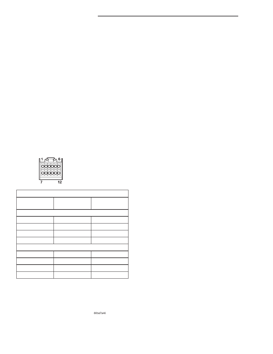
(4) Using two jumper wires, test the mirror as
shown in the Mirror Test chart (Fig. 1). If the mirror
tests OK, go to Step 5. If the mirror does not test
OK, replace the faulty mirror.
(5) Disconnect the 12-way door wire harness con-
nector from the door module connector receptacle.
Check all of the circuits of the door wire harness
between the connector for the mirror and the connec-
tor for the door module for opens or shorts. If all of
the circuits are OK, replace the faulty door module.
If any of the circuits are not OK, repair the open or
shorted circuit(s) as required.
(6) Use a DRB scan tool and the proper Diagnostic
Procedures manual to test and repair the faulty Pro-
grammable Communications Interface (PCI) data bus
communication between the two door modules.
NO MIRROR HEAT
If both mirror heaters are inoperative, refer to
Outside Mirror Heating Grid in the Rear Window
Defogger System section of Group 8N - Electrically
Heated Systems.
(1) Disconnect and isolate the battery negative
cable. Remove the front door trim panel on the side
of the inoperative mirror heater.
(2) Disconnect the 12-way door wire harness con-
nector from the door module connector receptacle.
Check for continuity between the heater switched
ground circuit cavity and the heater 12V supply cir-
cuit cavity of the 12-way door wire harness connector
for the door module. There should be continuity. If
OK, use a DRB scan tool and the proper Diagnostic
Procedures manual to test the door module and the
PCI data bus. If not OK, replace the faulty power
mirror unit.
NO MIRROR DIMMING (Driver Side Only)
(1) Test the operation of the automatic day/night
mirror. Refer to Automatic Day/Night Mirror in
the Inside Power Mirrors section of this group. If OK,
go to Step 2. If not OK, repair the automatic day/
night mirror unit as required.
(2) Disconnect and isolate the battery negative
cable. Remove the driver side front door trim panel.
(3) Disconnect the door wire harness connector
from the power mirror wire harness connector. Con-
nect a voltmeter between the electrochromatic (+)
and electrochromatic (–) circuit cavities of the door
wire harness connector for the power mirror. Turn on
the automatic day/night mirror system while observ-
ing the voltmeter. A voltmeter reading of 1.45
6 0.05
volts indicates a proper dimming signal is being
received at the door wire harness connector for the
power mirror. If OK, replace the faulty power mirror.
If not OK, repair the shorted or open electrochro-
matic (+) or electrochromatic (–) circuit(s) to the
automatic day/night mirror as required.
Fig. 1 Mirror Test
POWER MIRROR TEST
APPLY 12
VOLTS TO:
APPLY
GROUND TO:
MIRROR
REACTION
DRIVER SIDE
6
12
LEFT
12
6
RIGHT
11
12
UP
12
11
DOWN
PASSENGER SIDE
1
7
LEFT
7
1
RIGHT
8
7
UP
7
8
DOWN
8T - 4
POWER MIRROR SYSTEMS
WJ
DIAGNOSIS AND TESTING (Continued)