Jeep Grand Cherokee WJ. Manual - part 142


  Index      Jeep     Jeep Grand Cherokee WJ - service repair manual 2001 year


Search            


Content   ..  140  141  142  143   ..


Jeep Grand Cherokee WJ. Manual - part 142


(4) Install the center console bracket onto the stud

on the floor panel transmission tunnel in front of the
ACM.

(5) Install and tighten the nut that secures the

center console bracket to the stud on the floor panel
transmission tunnel. Tighten the nut to 28.2 N·m
(250 in. lbs.).

(6) Install the center floor console onto the floor

panel transmission tunnel. Refer to Floor Console
in the Removal and Installation section of Group 23 -
Body for the procedures.

(7) Do not reconnect the battery negative cable at

this time. Refer to Airbag System in the Diagnosis
and Testing section of this group for the proper pro-
cedures.

CLOCKSPRING

The clockspring cannot be repaired. It must be

replaced if faulty or damaged, or if the driver side
airbag has been deployed.

WARNING: THE AIRBAG SYSTEM IS A SENSITIVE,
COMPLEX ELECTROMECHANICAL UNIT. BEFORE
ATTEMPTING TO DIAGNOSE OR SERVICE ANY AIR-
BAG SYSTEM OR RELATED STEERING WHEEL,
STEERING

COLUMN,

OR

INSTRUMENT

PANEL

COMPONENTS YOU MUST FIRST DISCONNECT
AND ISOLATE THE BATTERY NEGATIVE (GROUND)
CABLE. THEN WAIT TWO MINUTES FOR THE SYS-
TEM CAPACITOR TO DISCHARGE BEFORE FUR-
THER SYSTEM SERVICE. THIS IS THE ONLY SURE
WAY TO DISABLE THE AIRBAG SYSTEM. FAILURE
TO DO THIS COULD RESULT IN ACCIDENTAL AIR-
BAG DEPLOYMENT AND POSSIBLE PERSONAL
INJURY.

REMOVAL

NOTE: Before starting this procedure, be certain to
turn the steering wheel until the front wheels are in
the straight-ahead position.

(1) Place the front wheels in the straight-ahead

position.

(2) Remove the driver side airbag module from the

steering wheel. Refer to Driver Side Airbag Mod-
ule 
in the Removal and Installation section of this
group for the procedures.

(3) Disconnect the steering wheel wire harness

connector from the upper clockspring connector
receptacle, which is located between the two upper
spokes of the armature within the hub cavity of the
steering wheel.

(4) Remove the nut that secures the steering wheel

armature to the steering column upper shaft, which
is located within the hub cavity of the steering wheel.

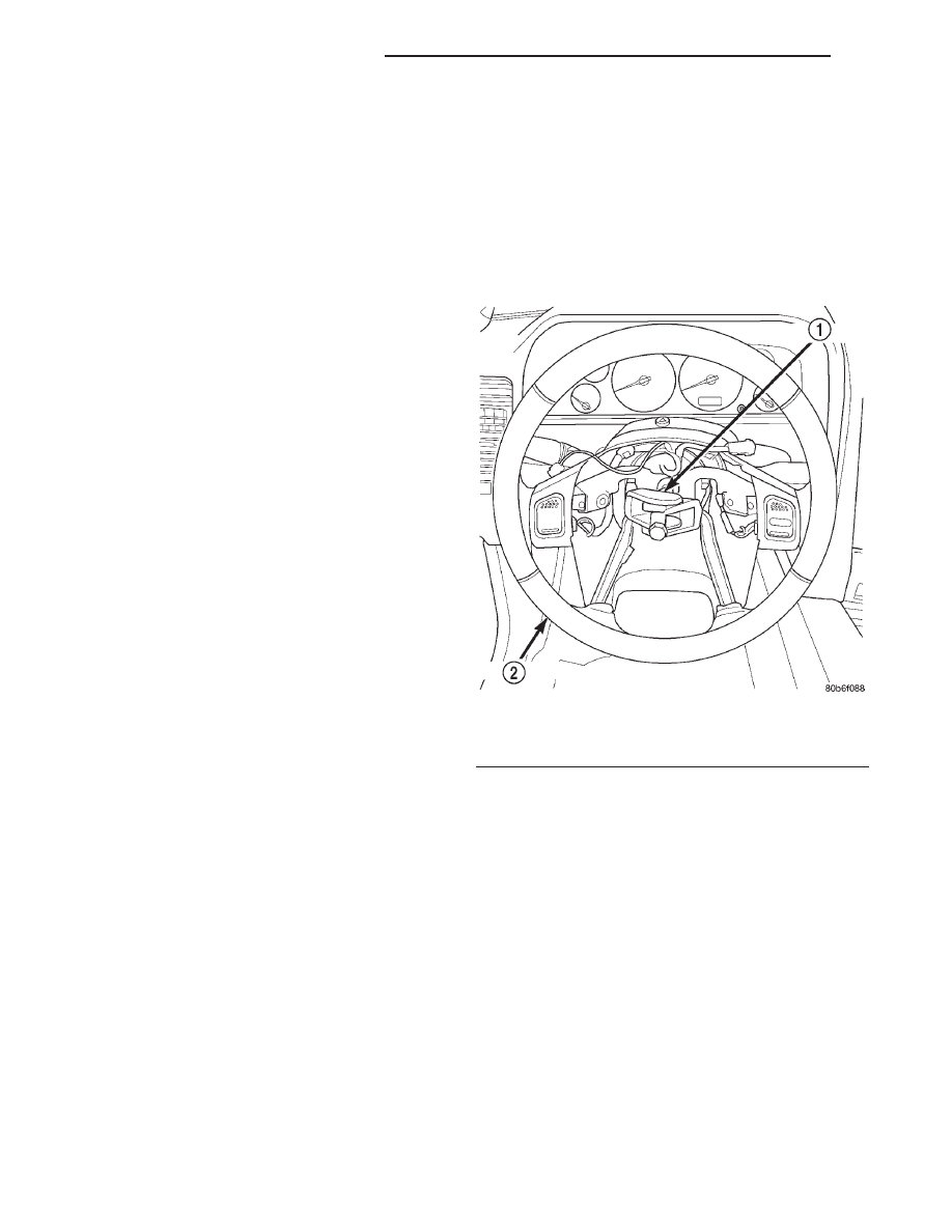
(5) Pull the steering wheel off of the steering col-

umn upper shaft spline using a two-jawed puller
(Special Tool C-3894-A) (Fig. 13). When installing the
puller onto the steering wheel, be certain that each
jaw of the puller is seated in the pocket that is cast
into the underside of the steering wheel armature on
each side of the hub (Fig. 14). Also, if the clockspring
is to be reused, be certain not to damage or deform
the clockspring case when positioning the jaws of the
puller below the steering wheel armature hub.

(6) Remove the screw that secures the lower tilting

steering column shroud to the steering column multi-
function switch mounting housing (Fig. 15).

(7) Unsnap the two halves of the tilting steering

column shroud from each other and remove both
halves from the steering column.

(8) Disconnect the two instrument panel wire har-

ness connectors from the lower clockspring connector
receptacles.

(9) Remove the two screws that secure the clock-

spring case to the multi-function switch mounting
housing (Fig. 16).

(10) Remove the clockspring from the steering col-

umn by sliding the clockspring hub up and off of the
steering column upper shaft. The clockspring cannot
be repaired. It must be replaced if faulty or damaged,
or if the driver side airbag has been deployed.

Fig. 13 Steering Wheel Remove/Install

1 – PULLER
2 – STEERING WHEEL

8M - 12

PASSIVE RESTRAINT SYSTEMS

WJ

REMOVAL AND INSTALLATION (Continued)

INSTALLATION

If the clockspring is not properly centered in rela-

tion to the steering wheel, steering shaft and steer-
ing gear, it may be damaged. Refer to Clockspring
Centering 
in the Adjustments section of this group
before installing or reinstalling a clockspring.

Service replacement clocksprings are shipped pre-

centered and with a locking pin installed. This lock-
ing pin should not be removed until the clockspring
has been installed on the steering column. If the
locking pin is removed before the clockspring is
installed on a steering column, the locking pin cannot
be reinstalled and the clockspring centering proce-
dure must be performed.

NOTE: Before starting this procedure, be certain
that the front wheels are still in the straight-ahead
position.

(1) While holding the centered clockspring hub and

case stationary in relationship to each other, slide
the clockspring down over the steering column upper
shaft.

(2) Align and seat the three pins in the clockspring

hub with the three holes in the hub of the turn sig-
nal cancelling cam. It should be noted that when the
clockspring is properly centered the uppermost pin in
the clockspring hub is an oblong pin, and it will only
fit in the oblong hole in the hub of the turn signal
cancelling cam.

Fig. 14 Steering Wheel Armature Pockets

1 – STEERING WHEEL POCKETS

Fig. 15 Steering Column Shrouds Remove/Install

1 – UPPER TILTING COLUMN SHROUD
2 – FIXED COLUMN SHROUD
3 – LOWER TILTING COLUMN SHROUD
4 – SCREW

Fig. 16 Clockspring Remove/Install

1 – OBLONG HOLE
2 – TURN SIGNAL CANCELLING CAM
3 – MULTI-FUNCTION SWITCH MOUNTING HOUSING
4 – RIGHT MULTI-FUNCTION SWITCH
5 – SCREW (2)
6 – OBLONG PIN
7 – CLOCKSPRING
8 – LEFT MULTI-FUNCTION SWITCH

WJ

PASSIVE RESTRAINT SYSTEMS

8M - 13

REMOVAL AND INSTALLATION (Continued)

(3) Align and seat the one pin and the two mount-

ing holes on the clockspring case to their respective
holes in the multi-function switch mounting housing.

(4) Install and tighten the two clockspring mount-

ing screws. Tighten the screws to 2.5 N·m (22 in.
lbs.).

(5) Reconnect the two instrument panel wire har-

ness connectors to the lower clockspring connector
receptacles.

(6) Position the lower tilting steering column

shroud to the steering column (Fig. 15). Install and
tighten the screw that secures the shroud to the
multi-function switch mounting housing. Tighten the
screw to 1.9 N·m (17 in. lbs.).

(7) Position the upper tilting column shroud to the

steering column with the hazard warning switch but-
ton inserted through the hole in the upper surface of
the shroud. Align the upper tilting steering column
shroud to the lower shroud and snap the two shroud
halves together.

(8) Install the steering wheel to the steering col-

umn upper shaft. Be certain to index the alignment
splines in the hub of the steering wheel armature
with the splines on the shaft. Pull the clockspring
wire harness through the hole between the two upper
steering wheel armature spokes.

(9) Install and tighten the steering wheel mount-

ing nut. Tighten the nut to 47 N·m (420 in. lbs.). Be
certain not to pinch the wire harnesses between the
steering wheel and the nut.

(10) Reconnect the steering wheel wire harness

connector to the upper clockspring connector recepta-
cle, which is located between the two upper spokes of
the armature within the hub cavity of the steering
wheel.

(11) Install the driver side airbag module onto the

steering wheel. Refer to Driver Side Airbag Mod-
ule 
in the Removal and Installation section of this
group for the procedures.

ADJUSTMENTS

CLOCKSPRING CENTERING

The clockspring is designed to wind and unwind

when the steering wheel is rotated, but is only
designed to rotate the same number of turns (about
five complete rotations) as the steering wheel can be
turned from stop to stop. Centering the clockspring
indexes the clockspring tape to other steering compo-
nents so that it can operate within its designed
travel limits. The rotor of a centered clockspring can
be rotated two and one-half turns in either direction
from the centered position, without damaging the
clockspring tape.

However, if the clockspring is removed for service

or if the steering column is disconnected from the

steering gear, the clockspring tape can change posi-
tion relative to the other steering components. The
clockspring must then be re-centered following com-
pletion of the service or the clockspring tape may be
damaged.

Service replacement clocksprings are shipped pre-

centered and with a locking pin installed. This lock-
ing pin should not be removed until the clockspring
has been installed on the steering column. If the
locking pin is removed before the clockspring is
installed on a steering column, the locking pin cannot
be reinstalled and the clockspring centering proce-
dure must be performed.

WARNING: THE AIRBAG SYSTEM IS A SENSITIVE,
COMPLEX ELECTROMECHANICAL UNIT. BEFORE
ATTEMPTING TO DIAGNOSE OR SERVICE ANY AIR-
BAG SYSTEM OR RELATED STEERING WHEEL,
STEERING

COLUMN,

OR

INSTRUMENT

PANEL

COMPONENTS YOU MUST FIRST DISCONNECT
AND ISOLATE THE BATTERY NEGATIVE (GROUND)
CABLE. THEN WAIT TWO MINUTES FOR THE SYS-
TEM CAPACITOR TO DISCHARGE BEFORE FUR-
THER SYSTEM SERVICE. THIS IS THE ONLY SURE
WAY TO DISABLE THE AIRBAG SYSTEM. FAILURE
TO DO THIS COULD RESULT IN ACCIDENTAL AIR-
BAG DEPLOYMENT AND POSSIBLE PERSONAL
INJURY.

NOTE: Before starting this procedure, be certain to
turn the steering wheel until the front wheels are in
the straight-ahead position.

(1) Place the front wheels in the straight-ahead

position.

(2) Remove the clockspring from the steering col-

umn. Refer to Clockspring in the Removal and
Installation section of this group for the procedures.

(3) Hold the clockspring case in one hand so that it

is oriented as it would be when it is installed on the
steering column.

(4) Use your other hand to rotate the clockspring

hub clockwise to the end of its travel. Do not apply
excessive torque.

(5) From the end of the clockwise travel, rotate the

hub about two and one-half turns counterclockwise.
It should be noted that when the clockspring is prop-
erly centered the arrows on the clockspring hub label
and the clockspring case should be aligned (Fig. 17),
and the uppermost pin in the clockspring hub should
be an oblong pin.

(6) The clockspring is now centered. Secure the

clockspring hub to the clockspring case to maintain
clockspring centering until it is reinstalled on the
steering column.

8M - 14

PASSIVE RESTRAINT SYSTEMS

WJ

REMOVAL AND INSTALLATION (Continued)

(7) The front wheels should still be in the straight-

ahead position. Install the clockspring onto the steer-

ing column. Refer to Clockspring in the Removal
and Installation section of this group for the proce-
dures.

SPECIAL TOOLS

PASSIVE RESTRAINT SYSTEMS

Fig. 17 Clockspring Alignment Arrows

1 – OBLONG HUB PIN
2 – CLOCKSPRING HUB
3 – DRIVER SIDE AIRBAG WIRE HARNESS CONNECTOR
4 – CLOCKSPRING CASE
5 – LOCKING PIN
6 – ALIGNMENT ARROWS
7 – LABEL

Puller C-3894-A

WJ

PASSIVE RESTRAINT SYSTEMS

8M - 15

ADJUSTMENTS (Continued)


Content   ..  140  141  142  143   ..