Jeep Grand Cherokee WJ. Manual - part 135


  Index      Jeep     Jeep Grand Cherokee WJ - service repair manual 2001 year


Search            


Content   ..  133  134  135  136   ..


Jeep Grand Cherokee WJ. Manual - part 135


DIAGNOSIS AND TESTING

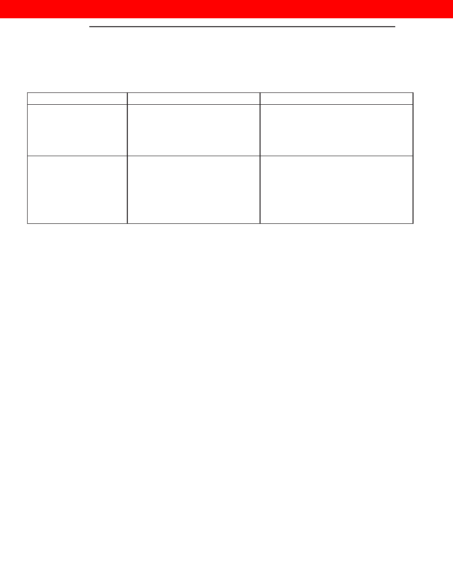
HEADLAMP LEVELING MOTOR DIAGNOSIS

CONDITION

POSSIBLE CAUSES

CORRECTION

ONE MOTOR DOES NOT
OPERATE

1. Poor connection at motor.

1. Secure connector on motor.

2. No voltage at motor.

2. Repair circuit. Refer to Group 8W,
Wiring.

3. Defective motor.

3. Replace motor.

BOTH MOTORS DO NOT
OPERATE

1. No voltage at headlamp leveling
switch.

1. Repair circuit or replace fuse. Refer to
Group 8W, Wiring.

2. No voltage at both motors.

2. Repair circuit or replace fuse. Refer to
Group 8W, Wiring.

3. Poor connection at motors.

3. Secure connectors on motors.

4. Both motors defective.

4. Replace motors.

8L - 2

LAMPS

WJ

DESCRIPTION AND OPERATION (Continued)

2000 JEEP GRAND CHEROKEE

HEADLAMP ALIGNMENT

TABLE OF CONTENTS

page

page

SERVICE PROCEDURES

HEADLAMP ALIGNMENT PREPARATION. . . . . . . . 3

HEADLAMP ALIGNMENT USING ALIGNMENT

SCREEN . . . . . . . . . . . . . . . . . . . . . . . . . . . . . . . 3

SERVICE PROCEDURES

HEADLAMP ALIGNMENT PREPARATION

(1) Verify the headlamps are on the low beam set-

ting.

(2) Verify that the headlamp leveling switch is in

the “0” position.

(3) Inspect and correct any damaged or defective

components that could interfere with proper head-
lamp alignment.

(4) Verify proper tire inflation.
(5) Clean headlamp lenses.
(6) Verify that luggage area is loaded as the vehi-

cle is routinely used.

(7) Fuel tank should be FULL. Add 2.94 kg (6.5

lbs.) of weight over the fuel tank for each estimated
gallon of missing fuel.

HEADLAMP ALIGNMENT USING ALIGNMENT
SCREEN

ALIGNMENT SCREEN PREPARATION

(1) Position vehicle on a level surface perpendicu-

lar to a flat wall 10 meters (32.8 ft.) away from front
of headlamp lens (Fig. 1).

(2) Place 75 kg in the driver’s seat to simulate the

ride height of the vehicle when driven.

(3) If necessary, tape a line on the floor 10 meters

(32.8 ft) away from and parallel to the wall.

(4) From the floor up 1.27 meters (5 ft), tape a line

on the wall at the centerline of the vehicle. Sight
along the centerline of the vehicle (from rear of vehi-
cle forward) to verify accuracy of the line placement.

(5) Rock vehicle side-to-side three times and allow

suspension to stabilize.

(6) Jounce front suspension three times by pushing

downward on front bumper and releasing.

(7) Measure the distance from the center of head-

lamp lens to the floor. Transfer measurement to the
alignment screen (with tape). Use this line for
up/down adjustment reference.

(8) Place a tape line 130 mm below and parallel to

the center of headlamp line.

(9) Measure distance from the centerline of the

vehicle to the center of each headlamp being aligned.
Transfer measurements to screen (with tape) to each
side of vehicle centerline. Use these lines for left/
right adjustment reference.

WJ

LAMPS

8L - 3

2000 JEEP GRAND CHEROKEE

HEADLAMP ADJUSTMENT

A properly aimed low beam headlamp will project a

high intensity light pattern on the screen with the
horizontal cut-off line aligned with the tape line 130
mm (5.12 in.) below the headlamp centerline (Fig. 1).
The intersection of the horizontal and 15 degree cut-
off lines in the projected pattern should align to the
intersection of the headlamp centerline vertical tape
line and the tape line 130 mm (5.12 in.) below the
headlamp horizontal centerline. The high beams on a
vehicle with aero headlamps cannot be aligned. The
high beam pattern should be correct when the low
beams are aligned properly.

To adjust headlamp alignment, rotate alignment

screws (Fig. 2) to achieve the specified low beam hot
spot pattern.

Fig. 2 Headlamp Beam Adustment Screws

1 – ADJUSTMENT SCREW LOCATION

Fig. 1 Headlamp Alignment Screen—Typical

1 – CENTER OF VEHICLE
2 – CENTER OF HEADLAMPS
3 – 130 mm
4 – FRONT OF HEADLAMP

5 – 15° CUT-OFF LINE
6 – 10 METERS (32.8 ft.)
7 – HORIZONTAL CUT-OFF LINE

8L - 4

LAMPS

WJ

SERVICE PROCEDURES (Continued)

2000 JEEP GRAND CHEROKEE

LAMP BULB SERVICE

TABLE OF CONTENTS

page

page

REMOVAL AND INSTALLATION

CENTER HIGH MOUNTED STOPLIGHT BULB . . . . 5
FRONT FOG LAMP BULB . . . . . . . . . . . . . . . . . . . 6
FRONT POSITION LAMP BULB . . . . . . . . . . . . . . . 6
FRONT TURN SIGNAL LAMP BULB . . . . . . . . . . . . 6

HIGHBEAM / LOWBEAM HEADLAMP BULBS . . . . 7
LICENSE PLATE LAMP BULBS . . . . . . . . . . . . . . . 7
SIDE REPEATER LAMP BULB . . . . . . . . . . . . . . . . 8
TAIL LAMP, REAR TURN SIGNAL, BACKUP

AND REAR FOG LAMP BULBS . . . . . . . . . . . . . 10

REMOVAL AND INSTALLATION

CENTER HIGH MOUNTED STOPLIGHT BULB

REMOVAL

(1) Remove the (2) screws retaining the center

high mounted stop lamp to the rear liftgate.

(2) Pull the lamp from the rear liftgate, rotate the

bulb socket 1/4 turn and pull from lamp housing (Fig.
1).

(3) Pull the bulb straight from its socket.

INSTALLATION

(1) Install the bulb in its socket.
(2) Verify lamp operation.

(3) Install the lamp socket in the lamp housing

(Fig. 2).

(4) Install the lamp housing in the rear liftgate

and install the retaining screws.

Fig. 1 Center High Mounted Stop Lamp

1 – CHMSL
2 – CHMSL BULB

Fig. 2 Center High Mounted Stop Lamp

1 – CHMSL
2 – CHMSL BULB

WJ

LAMPS

8L - 5

2000 JEEP GRAND CHEROKEE


Content   ..  133  134  135  136   ..