Jeep Grand Cherokee WJ. Manual - part 123
(10) Pull the multi-function switch mounting hous-
ing, the clockspring and both multi-function switches
from the top of the steering column as a unit (Fig.
11).
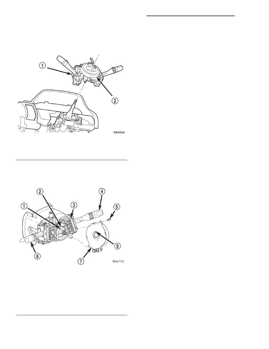
(11) Remove the two screws that secure the clock-
spring case to the multi-function switch mounting
housing (Fig. 12).
(12) Remove the clockspring from the multi-func-
tion switch mounting housing.
(13) Remove the turn signal and hazard warning
switch from the multi-function switch mounting
housing. Refer to Turn Signal and Hazard Warn-
ing Switch in the Removal and Installation section
of this group for the procedures.
(14) Remove the wiper and washer switch from the
multi-function switch mounting housing. Refer to
Wiper and Washer Switch in the Removal and
Installation section of Group 8K - Wiper and Washer
Systems for the procedures.
INSTALLATION
If the clockspring is not properly centered in rela-
tion to the steering wheel, steering shaft and steer-
ing gear, it may be damaged. Refer to Clockspring
Centering in the Adjustments section of Group 8M -
Passive Restraint Systems before installing or rein-
stalling a clockspring.
NOTE: Before starting this procedure, be certain
that the front wheels are still in the straight-ahead
position.
(1) Install the wiper and washer switch onto the
multi-function switch mounting housing. Refer to
Wiper and Washer Switch in the Removal and
Installation section of Group 8K - Wiper and Washer
Systems for the procedures.
(2) Install the turn signal and hazard warning
switch onto the multi-function switch mounting hous-
ing. Refer to Turn Signal and Hazard Warning
Switch in the Removal and Installation section of
this group for the procedures.
(3) Rotate the turn signal cancelling cam in the
multi-function switch mounting housing until the
alignment hole in the one cam lobe is aligned with
the alignment hole in the back of the housing. The
oblong hole in the hub of the cam should now be at
the top, and the locating tab in the hub of the cam
should be at the bottom (Fig. 13).
(4) While holding the centered clockspring hub and
case stationary in relationship to each other, align
and seat the three pins in the clockspring hub with
the three holes in the hub of the turn signal cancel-
ling cam. It should be noted that when the clock-
spring is properly centered the uppermost pin in the
clockspring hub is an oblong pin, and it will only fit
in the oblong hole in the hub of the turn signal can-
celling cam.
(5) Align and seat the one pin and the two mount-
ing holes on the clockspring case to their respective
holes in the multi-function switch mounting housing.
(6) Install and tighten the two clockspring mount-
ing screws. Tighten the screws to 2.5 N·m (22 in.
lbs.).
Fig. 11 Multi-Function Switch Mounting Housing
Remove/install
1 – MULTIFUNCTION SWITCH
2 – CLOCK SPRING
Fig. 12 Clockspring Remove/Install
1 – OBLONG HOLE
2 – TURN SIGNAL CANCELLING CAM
3 – MULTI-FUNCTION SWITCH MOUNTING HOUSING
4 – RIGHT MULTI-FUNCTION SWITCH
5 – SCREW (2)
6 – OBLONG PIN
7 – CLOCKSPRING
8 – LEFT MULTI-FUNCTION SWITCH
8J - 12
TURN SIGNAL AND HAZARD WARNING SYSTEMS
WJ
REMOVAL AND INSTALLATION (Continued)