Jeep Grand Cherokee WJ. Manual - part 119


  Index      Jeep     Jeep Grand Cherokee WJ - service repair manual 2001 year


Search            


Content   ..  117  118  119  120   ..


Jeep Grand Cherokee WJ. Manual - part 119


SERVO CABLE—4.0L ENGINE

REMOVAL

(1) Disconnect negative battery cable at battery.
(2) Remove air box housing from throttle body.
(3) Using finger pressure only, remove speed con-

trol cable connector at throttle body bellcrank pin by
pushing connector off bellcrank pin towards drivers
side of vehicle (Fig. 4). DO NOT try to pull con-
nector off perpendicular to the bellcrank pin.
Connector will be broken.

(4) Remove cable from cable guide at top of valve

cover.

(5) Squeeze 2 release tabs (Fig. 4) on sides of cable

at bracket and push cable out of bracket.

(6) Remove servo cable from servo. Refer to Speed

Control Servo Removal/Installation.

INSTALLATION

(1) Install end of cable to speed control servo.

Refer to Speed Control Servo Removal/Installation.

(2) Install cable into mounting bracket (snaps in).
(3) Install speed control cable connector at throttle

body bellcrank pin (snaps on).

(4) Connect negative battery cable at battery.
(5) Before

starting

engine,

operate

accelerator

pedal to check for any binding.

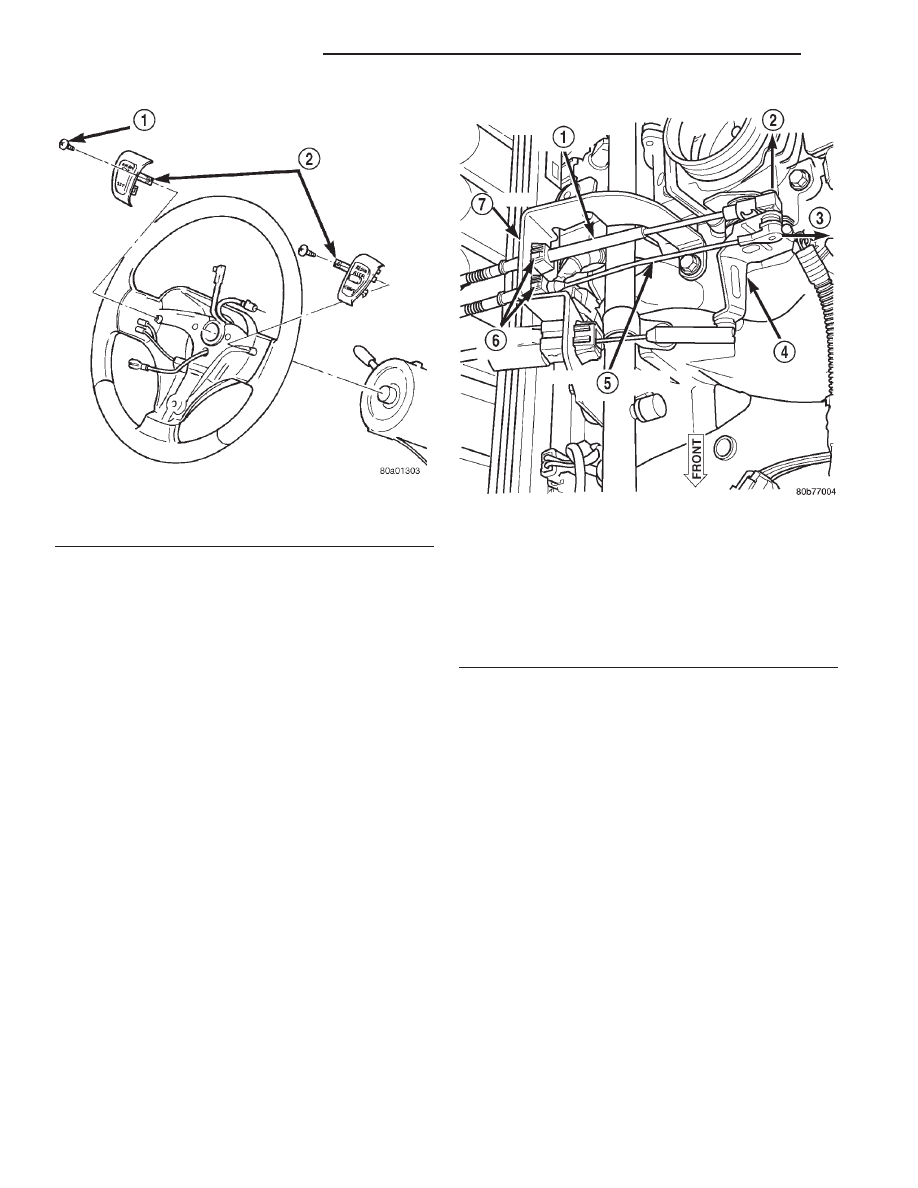
Fig. 3 Speed Control Switches

1 – MOUNTING SCREW
2 – SPEED CONTROL SWITCHES

Fig. 4 Speed Control Cable at Bell Crank—4.0L

Engine

1 – ACCELERATOR CABLE
2 – OFF
3 – OFF
4 – THROTTLE BODY BELLCRANK
5 – SPEED CONTROL CABLE
6 – RELEASE TABS
7 – BRACKET

8H - 6

SPEED CONTROL SYSTEM

WJ

REMOVAL AND INSTALLATION (Continued)

SERVO CABLE—4.7L V-8 ENGINE

REMOVAL

(1) Disconnect negative battery cable at battery.
(2) Remove air box housing from throttle body.
The accelerator cable must be partially removed to

gain access to speed control cable.

(3) Using finger pressure only, disconnect accelera-

tor cable connector at throttle body bellcrank pin by
pushing connector off bellcrank pin towards front of
vehicle (Fig. 5). DO NOT try to pull connector off
perpendicular to the bellcrank pin. Connector
will be broken.

(4) Lift accelerator cable from top of cable cam

(Fig. 5).

(5) Press tab (Fig. 6) to release plastic cable mount

from bracket. Press on tab only enough to
release cable from bracket. If tab is pressed too
much, it will be broken. 
Slide plastic mount (Fig.
6) towards passenger side of vehicle to remove cable
from bracket.

(6) Using finger pressure only, disconnect speed

control cable connector at throttle body bellcrank pin
by pushing connector off bellcrank pin towards front
of vehicle (Fig. 5). DO NOT try to pull connector
off perpendicular to the bellcrank pin. Connec-
tor will be broken.

(7) Slide speed control cable plastic mount towards

passenger side of vehicle to remove cable from
bracket (Fig. 7).

(8) Remove servo cable from servo. Refer to Speed

Control Servo Removal/Installation.

INSTALLATION

(1) Install end of cable to speed control servo.

Refer to Speed Control Servo Removal/Installation.

(2) Slide speed control cable plastic mount into

bracket.

(3) Install speed control cable connector onto throt-

tle body bellcrank pin (snaps on).

(4) Slide

accelerator

cable

plastic

mount

into

bracket. Continue sliding until tab (Fig. 6) is aligned
to hole in mounting bracket.

(5) Route accelerator cable over top of cable cam

(Fig. 5).

(6) Install accelerator cable connector onto throttle

body bellcrank pin (snaps on).

(7) Install air box housing to throttle body.
(8) Connect negative battery cable at battery.
(9) Before

starting

engine,

operate

accelerator

pedal to check for any binding.

Fig. 5 Cable Connectors at Bell Crank—4.7L V-8 Engine

1 – THROTTLE BODY
2 – SPEED CONTROL CABLE CONNECTOR
3 – OFF
4 – OFF
5 – ACCELERATOR CABLE CONNECTOR
6 – CABLE CAM
7 – BELLCRANK

Fig. 6 Accelerator Cable Release Tab—4.7L V-8 Engine

1 – ACCELERATOR CABLE
2 – PLASTIC CABLE MOUNT
3 – PRESS TAB FOR REMOVAL
4 – CABLE BRACKET
5 – SLIDE FOR REMOVAL

WJ

SPEED CONTROL SYSTEM

8H - 7

REMOVAL AND INSTALLATION (Continued)

VACUUM RESERVOIR

The vacuum reservoir is located in the right/front

corner of the vehicle behind the front bumper fascia
(Fig. 8).

REMOVAL

(1) Remove front bumper and grill assembly.
(2) Remove 1 support bolt near front of reservoir

(Fig. 8).

(3) Remove 2 reservoir mounting bolts.
(4) Remove reservoir from vehicle to gain access to

vacuum hose (Fig. 9). Disconnect vacuum hose from
reservoir fitting at rear of reservoir.

INSTALLATION

(1) Connect vacuum hose to reservoir.
(2) Install reservoir and tighten 2 bolts to 3 N·m

(25 in. lbs.) torque.

(3) Install front bumper and grill assembly.

Fig. 7 Speed Control Cable at Bracket—4.7L V-8

Engine

1 – PLASTIC CABLE MOUNT
2 – SPEED CONTROL CABLE
3 – BRACKET
4 – SLIDE FOR REMOVAL

Fig. 8 Vacuum Reservoir Location

1 – RADIATOR FAN RELAY
2 – VACUUM RESERVOIR
3 – BOLT
4 – RIGHT FRONT FENDER

Fig. 9 Vacuum Reservoir Removal/Installation

1 – VACUUM HOSE
2 – RADIATOR
3 – VACUUM RESERVOIR

8H - 8

SPEED CONTROL SYSTEM

WJ

REMOVAL AND INSTALLATION (Continued)

SPECIFICATIONS

TORQUE CHART

Description

Torque

Servo Mounting Bracket-to-Servo Nuts . . . 8.5 N·m

(75 in. lbs.)

Servo Mounting Bracket-to-Body Nuts . 28 N·m

66

N·m (250 in. lbs.

650 in.lbs.)

Switch Module Mounting Screws . .6–1 N·m (6–9 in.

lbs.)

Vacuum Reservoir Mounting Bolts . . . 3 N·m (25 in.

lbs.)

WJ

SPEED CONTROL SYSTEM

8H - 9


Content   ..  117  118  119  120   ..