Jeep Grand Cherokee WJ. Manual - part 117


  Index      Jeep     Jeep Grand Cherokee WJ - service repair manual 2001 year


Search            


Content   ..  115  116  117  118   ..


Jeep Grand Cherokee WJ. Manual - part 117


WARNING: ON VEHICLES EQUIPPED WITH AIR-
BAGS,

REFER

TO

GROUP

8M

-

PASSIVE

RESTRAINT SYSTEMS BEFORE ATTEMPTING ANY
STEERING

WHEEL,

STEERING

COLUMN,

OR

INSTRUMENT PANEL COMPONENT DIAGNOSIS OR
SERVICE. FAILURE TO TAKE THE PROPER PRE-
CAUTIONS COULD RESULT IN ACCIDENTAL AIR-
BAG DEPLOYMENT AND POSSIBLE PERSONAL
INJURY.

(1) Remove the horn relay from the PDC. Refer to

Horn Relay in the Removal and Installation section
of this group for the procedures.

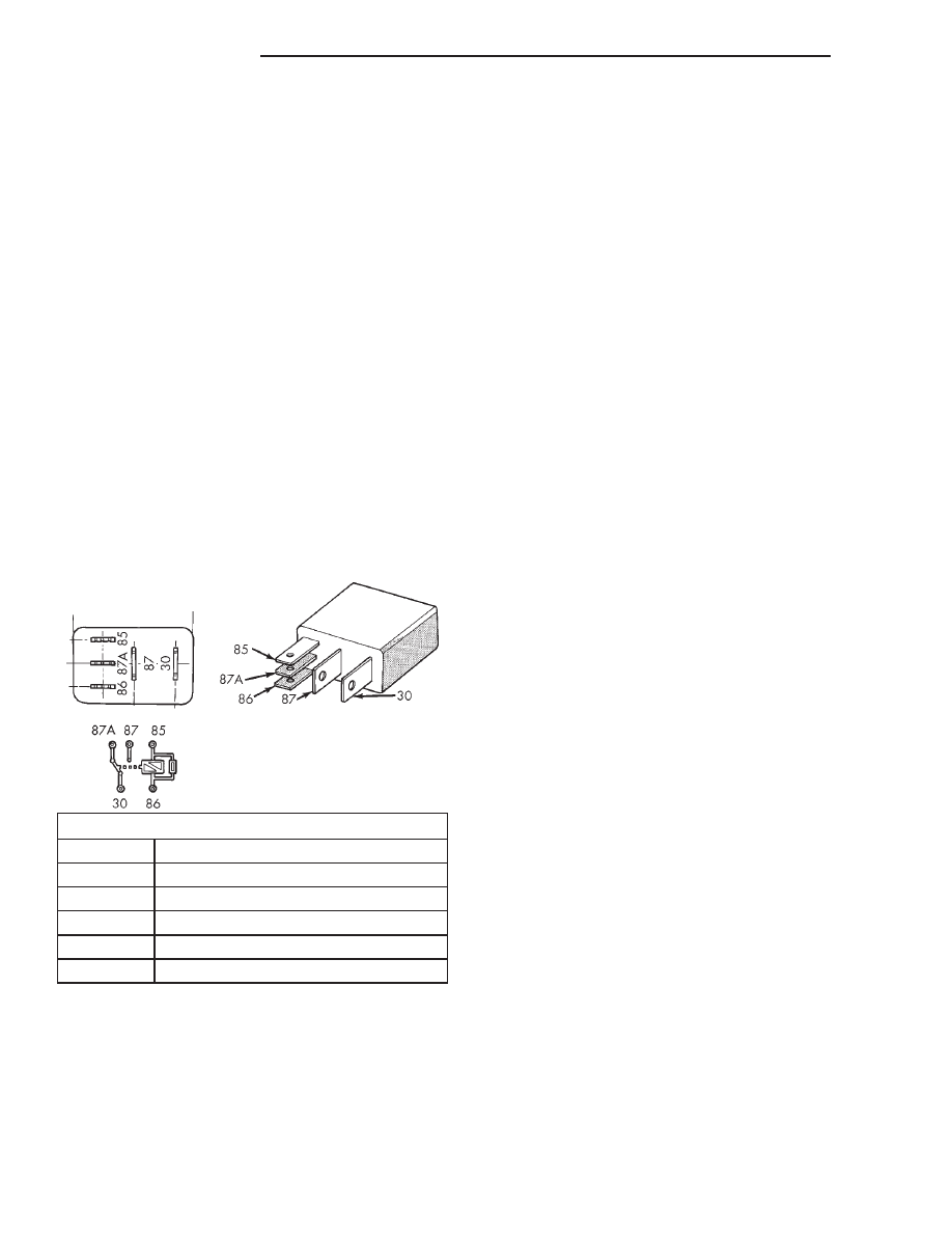
(2) A relay in the de-energized position should

have continuity between terminals 87A and 30, and
no continuity between terminals 87 and 30. If OK, go
to Step 3. If not OK, replace the faulty relay.

(3) Resistance between terminals 85 and 86 (elec-

tromagnet) should be 75

6 5 ohms. If OK, go to Step

4. If not OK, replace the faulty relay.

(4) Connect a battery to terminals 85 and 86.

There should now be continuity between terminals
30 and 87, and no continuity between terminals 87A
and 30. If OK, perform the Relay Circuit Test that
follows. If not OK, replace the faulty relay.

RELAY CIRCUIT TEST

(1) The relay common feed terminal cavity (30) is

connected to battery voltage and should be hot at all
times. If OK, go to Step 2. If not OK, repair the open
circuit to the fuse in the PDC as required.

(2) The relay normally closed terminal (87A) is

connected to terminal 30 in the de-energized position,
but is not used for this application. Go to Step 3.

(3) The relay normally open terminal (87) is con-

nected to the common feed terminal (30) in the ener-
gized position. This terminal supplies battery voltage
to the horn(s). There should be continuity between
the cavity for relay terminal 87 and the horn relay
output circuit cavity of each horn wire harness con-
nector at all times. If OK, go to Step 4. If not OK,
repair the open circuit to the horn(s) as required.

(4) The coil battery terminal (86) is connected to

the electromagnet in the relay. It is connected to bat-
tery voltage and should be hot at all times. Check for
battery voltage at the cavity for relay terminal 86. If
OK, go to Step 5. If not OK, repair the open circuit to
the fuse in the PDC as required.

(5) The coil ground terminal (85) is connected to

the electromagnet in the relay. It is grounded
through the horn switch when the horn switch is
depressed. The horn relay coil ground terminal can
also be grounded by the Body Control Module (BCM)
in response to certain inputs related to the RKE sys-
tem or the Vehicle Theft Security System. Check for
continuity to ground at the cavity for relay terminal
85. There should be continuity with the horn switch
depressed, and no continuity with the horn switch
released. If not OK, refer to Horn Switch in the
Diagnosis and Testing section of this group.

HORN

For complete circuit diagrams, refer to Horn/Ci-

gar Lighter/Power Outlet in the Contents of
Group 8W - Wiring Diagrams.

(1) Disconnect the wire harness connector(s) from

the horn connector receptacle(s). Measure the resis-
tance between the ground circuit cavity of the horn(s)
wire harness connector(s) and a good ground. There
should be no measurable resistance. If OK, go to Step
2. If not OK, repair the open ground circuit to ground
as required.

(2) Check for battery voltage at the horn relay out-

put circuit cavity of the horn(s) wire harness connec-
tor(s). There should be zero volts. If OK, go to Step 3.
If not OK, repair the shorted horn relay output cir-
cuit or replace the faulty horn relay as required.

(3) Depress the horn switch. There should now be

battery voltage at the horn relay output circuit cavity
of the horn(s) wire harness connector(s). If OK,
replace the faulty horns. If not OK, repair the open
horn relay output circuit to the horn relay as
required.

TERMINAL LEGEND

NUMBER

IDENTIFICATION

30

COMMON FEED

85

COIL GROUND

86

COIL BATTERY

87

NORMALLY OPEN

87A

NORMALLY CLOSED

Fig. 1 Horn Relay

8G - 4

HORN SYSTEMS

WJ

DIAGNOSIS AND TESTING (Continued)

REMOVAL AND INSTALLATION

HORN SWITCH

WARNING:

ON

VEHICLES

EQUIPPED

WITH

AIRBAGS,

REFER TO GROUP 8M - PASSIVE RESTRAINT SYS-
TEMS

BEFORE

ATTEMPTING

ANY

STEERING

WHEEL, STEERING COLUMN, OR INSTRUMENT
PANEL COMPONENT DIAGNOSIS OR SERVICE.
FAILURE TO TAKE THE PROPER PRECAUTIONS
COULD RESULT IN ACCIDENTAL AIRBAG DEPLOY-
MENT AND POSSIBLE PERSONAL INJURY.

THE HORN SWITCH IS INTEGRAL TO THE

DRIVER SIDE AIRBAG MODULE. SERVICE OF THIS
COMPONENT SHOULD BE PERFORMED ONLY BY
CHRYSLER-TRAINED AND AUTHORIZED DEALER
SERVICE TECHNICIANS. FAILURE TO TAKE THE
PROPER PRECAUTIONS OR TO FOLLOW THE
PROPER PROCEDURES COULD RESULT IN ACCI-
DENTAL, INCOMPLETE, OR IMPROPER AIRBAG
DEPLOYMENT AND POSSIBLE OCCUPANT INJU-
RIES.

REMOVAL

(1) Disconnect and isolate the battery negative

cable.

(2) Remove the trim cover from the driver side air-

bag module. Refer to Driver Side Airbag Module
Trim Cover 
in the Removal and Installation section
of Group 8M - Passive Restraint Systems for the pro-
cedures.

(3) Remove the horn switch and tray as a unit

from the pouch on the retaining strap of the driver
side airbag module (Fig. 2).

INSTALLATION

(1) Install the horn switch and tray as a unit into

the pouch on the retaining strap of the driver side
airbag module. Be certain that the tray is facing the
airbag module, that the horn switch is facing the
trim cover, that the horn switch feed wire is on the
left, and that the horn switch ground wire is on the
right.

(2) Install the trim cover onto the driver side air-

bag module. Refer to Driver Side Airbag Module
Trim Cover 
in the Removal and Installation section
of Group 8M - Passive Restraint Systems for the pro-
cedures.

(3) Reconnect the battery negative cable.

HORN RELAY

REMOVAL

(1) Disconnect and isolate the battery negative

cable.

(2) Remove the cover from the Power Distribution

Center (PDC) (Fig. 3).

(3) See the fuse and relay layout label affixed to

the underside of the PDC cover for horn relay iden-
tification and location.

(4) Remove the horn relay from the PDC.

INSTALLATION

(1) See the fuse and relay layout label affixed to

the underside of the PDC cover for the proper horn
relay location.

(2) Position the horn relay in the proper receptacle

in the PDC.

(3) Align the horn relay terminals with the termi-

nal cavities in the PDC receptacle.

(4) Push down firmly on the horn relay until the

terminals are fully seated in the terminal cavities in
the PDC receptacle.

(5) Install the cover onto the PDC.
(6) Reconnect the battery negative cable.

Fig. 2 Horn Switch Remove/Install

1 – HORN SWITCH GROUND WIRE EYELET
2 – HORN SWITCH
3 – AIRBAG RETAINING STRAP
4 – POUCH
5 – DRIVER SIDE AIRBAG MODULE (TRIM COVER REMOVED)
6 – TRAY
7 – HORN SWITCH FEED WIRE CONNECTOR

WJ

HORN SYSTEMS

8G - 5

HORN

REMOVAL

(1) Disconnect and isolate the battery negative

cable.

(2) Raise and support the vehicle.
(3) Remove the lower front half of the inner liner

from the right front fender wheel house. Refer to
Front Fender in the Removal and Installation sec-
tion of Group 23 - Body for the procedures.

(4) Reach through the front of the right front

fender wheel house opening to access and disconnect
the two right headlamp and dash wire harness con-
nectors from the horn connector receptacles (Fig. 4).
Be certain to disengage the connector lock tabs
before disconnecting them from the horn connector
receptacles.

(5) Remove the screw that secures the horn

mounting bracket to the right extension of the radi-
ator closure assembly.

(6) Remove both horns and the mounting bracket

from the right extension of the radiator closure
assembly as a unit.

INSTALLATION

(1) Position both horns and the mounting bracket

onto the right extension of the radiator closure
assembly as a unit.

(2) Install and tighten the screw that secures the

horn mounting bracket to the right extension of the
radiator closure assembly. Tighten the screw to 11.3
N·m (100 in. lbs.).

(3) Reconnect the two right headlamp and dash

wire harness connectors to the horn connector recep-
tacles. Be certain to engage the connector lock tabs
after reconnecting them to the horn connector recep-
tacles.

(4) Install the lower front half of the inner liner to

the right front fender wheel house. Refer to Front
Fender 
in the Removal and Installation section of
Group 23 - Body for the procedures.

(5) Lower the vehicle.
(6) Reconnect the battery negative cable.

Fig. 3 Power Distribution Center

1 – RIGHT FENDER
2 – BATTERY
3 – POWER DISTRIBUTION CENTER
4 – COVER

Fig. 4 Horns Remove/Install

1 – RADIATOR CLOSURE ASSEMBLY
2 – HORNS AND MOUNTING BRACKET
3 – RIGHT HEADLAMP AND DASH WIRE HARNESS

CONNECTORS

8G - 6

HORN SYSTEMS

WJ

REMOVAL AND INSTALLATION (Continued)

SPEED CONTROL SYSTEM

TABLE OF CONTENTS

page

page

DESCRIPTION AND OPERATION

SPEED CONTROL SYSTEM . . . . . . . . . . . . . . . . . 1
SPEED CONTROL SERVO. . . . . . . . . . . . . . . . . . . 2
SPEED CONTROL SOLENOID CIRCUITS . . . . . . . 2
SPEED CONTROL SWITCHES . . . . . . . . . . . . . . . 2
BRAKE LAMP SWITCH. . . . . . . . . . . . . . . . . . . . . 3
SERVO CABLE . . . . . . . . . . . . . . . . . . . . . . . . . . . 3
VACUUM RESERVOIR . . . . . . . . . . . . . . . . . . . . . 3

DIAGNOSIS AND TESTING

ROAD TEST . . . . . . . . . . . . . . . . . . . . . . . . . . . . . 3

VACUUM SUPPLY TEST . . . . . . . . . . . . . . . . . . . . 4

REMOVAL AND INSTALLATION

SPEED CONTROL SERVO. . . . . . . . . . . . . . . . . . . 4
SPEED CONTROL SWITCHES . . . . . . . . . . . . . . . 5
SERVO CABLE—4.0L ENGINE . . . . . . . . . . . . . . . 6
SERVO CABLE—4.7L V-8 ENGINE. . . . . . . . . . . . 7
VACUUM RESERVOIR . . . . . . . . . . . . . . . . . . . . . 8

SPECIFICATIONS

TORQUE CHART . . . . . . . . . . . . . . . . . . . . . . . . . . 9

DESCRIPTION AND OPERATION

SPEED CONTROL SYSTEM

DESCRIPTION

The speed control system is electronically con-

trolled and vacuum operated. Electronic control of
the speed control system is integrated into the Pow-
ertrain Control Module (PCM). The controls consist
of

two

steering

wheel

mounted

switches.

The

switches are labeled: ON/OFF, RES/ACCEL, SET,
COAST, and CANCEL.

The system is designed to operate at speeds above

30 mph (50 km/h).

WARNING: THE USE OF SPEED CONTROL IS NOT
RECOMMENDED WHEN DRIVING CONDITIONS DO
NOT PERMIT MAINTAINING A CONSTANT SPEED,
SUCH AS IN HEAVY TRAFFIC OR ON ROADS THAT
ARE WINDING, ICY, SNOW COVERED, OR SLIP-
PERY.

OPERATION

When speed control is selected by depressing the

ON switch, the PCM allows a set speed to be stored
in PCM RAM for speed control. To store a set speed,
depress the SET switch while the vehicle is moving
at a speed between 35 and 85 mph. In order for the
speed control to engage, the brakes cannot be
applied, nor can the gear selector be indicating the
transmission is in Park or Neutral.

The speed control can be disengaged manually by:
• Stepping on the brake pedal

• Depressing the OFF switch

• Depressing the CANCEL switch.

• Depressing the clutch pedal (if equipped).

NOTE: Depressing the OFF switch or turning off
the ignition switch will erase the set speed stored
in the PCM.

For added safety, the speed control system is pro-

grammed to disengage for any of the following condi-
tions:

• An indication of Park or Neutral

• A rapid increase rpm (indicates that the clutch

has been disengaged)

• Excessive engine rpm (indicates that the trans-

mission may be in a low gear)

• The speed signal increases at a rate of 10 mph

per second (indicates that the coefficient of friction
between the road surface and tires is extremely low)

• The speed signal decreases at a rate of 10 mph

per second (indicates that the vehicle may have
decelerated at an extremely high rate)

Once the speed control has been disengaged,

depressing the RES/ACCEL switch (when speed is
greater than 30 mph) restores the vehicle to the tar-
get speed that was stored in the PCM.

While the speed control is engaged, the driver can

increase the vehicle speed by depressing the RES/AC-
CEL switch. The new target speed is stored in the
PCM when the RES/ACCEL is released. The PCM
also has a “tap-up

9 feature in which vehicle speed

increases at a rate of approximately 2 mph for each
momentary switch activation of the RES/ACCEL
switch.

A “tap down” feature is used to decelerate without

disengaging the speed control system. To decelerate
from an existing recorded target speed, momentarily

WJ

SPEED CONTROL SYSTEM

8H - 1


Content   ..  115  116  117  118   ..