Content .. 1127 1128 1129 1130 ..
Jeep Grand Cherokee WJ. Manual - part 1129
intermittent front wiper positions. The wiper stalk
is pulled toward the driver to activate the wind-
shield washer system. Both the front wiper and
front washer motors will operate continuously for
as long as the stalk is held in the momentary
FRONT WASH position.
Another rotary switch on the wiper multi-
function switch stalk is rotated to select the desired
rear wiper speed (ON or DELAY). The wiper stalk
is pushed toward the instrument panel to activate
the rear liftglass washer system. Both the rear
wiper and rear washer motors will operate contin-
uously for as long as the stalk is held in the
momentary REAR WASH position.
If any part of the right multi-function switch
stalk is faulty or damaged, the entire wiper multi-
function switch assembly must be replaced.
3.17.2
REAR WIPER SYSTEM
Five circuits feed the rear wiper module. It has
two high current circuits, battery (B+) and ground,
that run the motor. The remaining three circuits
are low current control circuits.
Two of these circuits come from the rear wiper
switch on the right multi-function switch stalk.
These circuits are referred to as the rear wiper
motor control circuit and the rear wiper motor
intermittent control circuit. When the rear wiper
switch is in the Off position, both of these circuits
are open and the wiper module parks or remains
parked. When the rear wiper switch is in the
Intermittent position, the intermittent control cir-
cuit is switched to ignition voltage, the motor
control circuit is open and the wiper is in the
intermittent modes. When the rear wiper switch is
in the On position, the intermittent control circuit
is open and the motor control circuit is switched to
ignition voltage and the wiper is in continuous
wipe mode.
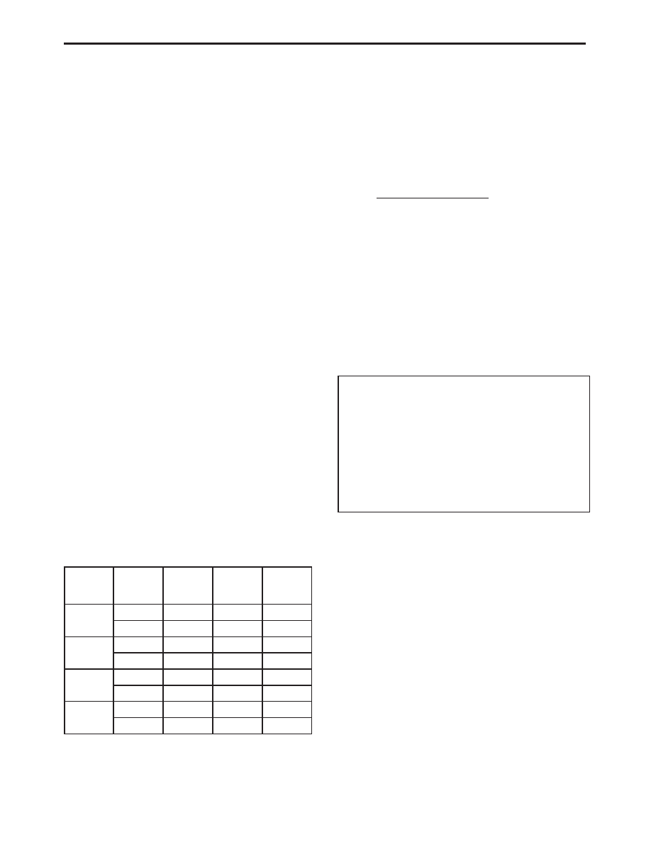
REAR WIPER SYSTEM CONTROL CIRCUITS
REAR
WIPER
SWITCH
POSITION
DELAY
CIRCUIT
CONTINU-
OUS CIR-
CUIT
AJAR
CIRCUIT
WIPER
MODE
OFF
OPEN
OPEN
OPEN
PARKED
OPEN
OPEN
GROUND
PARKED
DEL
IGNITION
OPEN
OPEN
DELAY
IGNITION
OPEN
GROUND
PARKED
ON
OPEN
IGNITION
OPEN
ON
OPEN
IGNITION
GROUND
PARKED
WASH
IGNITON
IGNITION
OPEN
WASH
IGNITION
IGNITION
GROUND
PARKED
The third control circuit is the AJAR circuit. This
circuit is fed by the flip-up glass ajar switch. When
the flip-up glass is closed the ajar switch is open
and the rear wiper module functions normally.
When the flip-up glass is open the ajar switch
closes and the circuit provides ground to the mod-
ule. This ground signal indicates to the rear wiper
module that it should park if operating or not allow
operation if parked.
3.18
USING THE DRBIII
T
Refer to the DRBIII
t user’s guide for instruc-
tions and assistance with reading trouble codes,
erasing trouble codes and other DRBIII
t functions.
3.18.1
DRBIII
T ERROR MESSAGES AND
BLANK SCREEN
Under normal operation, the DRBIII
t will dis-
play one of only two error messages:
–User-Requested
WARM
Boot
or
User-
Requested COLD Boot
This is a sample of such an error message dis-
play:
ver: 2.14
date: 26 Jul93
file: key_itf.cc
date: Jul 26 1993
line: 548
err: 0x1
User-Requested COLD Boot
Press MORE to switch between this display
and the application screen.
Press F4 when done noting information.
3.18.2
DRBIII
T DOES NOT POWER UP
If the LED’s do not light or no sound is emitted at
start up, check for loose cable connections or a bad
cable. Check the vehicle battery voltage (data link
connector cavity 16). A minimum of 11 volts is
required to adequately power the DRBIII
t.
If all connections are proper between the
DRBIII
t and the vehicle or other devices, and the
vehicle battery is fully charged, and inoperative
DRBIII
t may be the result of faulty cable or vehicle
wiring.
19
GENERAL INFORMATION