Jeep Grand Cherokee WJ. Manual - part 111


  Index      Jeep     Jeep Grand Cherokee WJ - service repair manual 2001 year


Search            


Content   ..  109  110  111  112   ..


Jeep Grand Cherokee WJ. Manual - part 111


(4) Verify switch operation.
(5) Push the headlamp switch straight into the

cluster bezel until retaining tabs lock it in place.

REAR FOG LAMP SWITCH

WARNING: ON VEHICLES EQUIPPED WITH AIR-
BAGS,

REFER

TO

GROUP

8M

-

PASSIVE

RESTRAINT SYSTEMS BEFORE ATTEMPTING ANY
STEERING

WHEEL,

STEERING

COLUMN,

OR

INSTRUMENT PANEL COMPONENT DIAGNOSIS OR
SERVICE. FAILURE TO TAKE THE PROPER PRE-
CAUTIONS COULD RESULT IN ACCIDENTAL AIR-
BAG DEPLOYMENT AND POSSIBLE PERSONAL
INJURY.

For the removal and installation procedure of the

rear fog lamp switch. Refer to the turn signal switch
removal and installation procedure in Group 8J,
Turn Signal and Hazard Warning Systems.

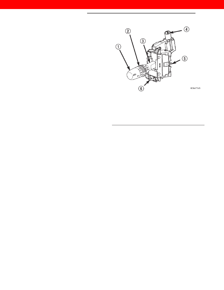
Fig. 3 Lighting Multi-Function Switch

1 – EXTERIOR LIGHTING CONTROL
2 – INTERIOR LIGHTING CONTROL
3 – CONTROL STALK
4 – HAZARD WARNING BUTTON
5 – CANCEL ACTUATOR
6 – LEFT (LIGHTING) MULTI-FUNCTION SWITCH

8E - 2

INSTRUMENT PANEL SYSTEMS

WJ

REMOVAL AND INSTALLATION (Continued)

2000 JEEP GRAND CHEROKEE

AUDIO SYSTEMS

TABLE OF CONTENTS

page

page

DESCRIPTION AND OPERATION

AUDIO SYSTEM . . . . . . . . . . . . . . . . . . . . . . . . . . 1
COMPACT DISC CHANGER . . . . . . . . . . . . . . . . . 2
RADIO RECEIVER . . . . . . . . . . . . . . . . . . . . . . . . . 2
REMOTE RADIO SWITCH. . . . . . . . . . . . . . . . . . . 3
SPEAKER SYSTEM . . . . . . . . . . . . . . . . . . . . . . . . 3
ANTENNA . . . . . . . . . . . . . . . . . . . . . . . . . . . . . . . 4
POWER AMPLIFIER . . . . . . . . . . . . . . . . . . . . . . . 4
RADIO NOISE SUPPRESSION . . . . . . . . . . . . . . . 4

DIAGNOSIS AND TESTING

AUDIO SYSTEM . . . . . . . . . . . . . . . . . . . . . . . . . . 5
RADIO RECEIVER . . . . . . . . . . . . . . . . . . . . . . . . . 6
COMPACT DISC CHANGER . . . . . . . . . . . . . . . . . 7
REMOTE RADIO SWITCH. . . . . . . . . . . . . . . . . . . 8

SPEAKER . . . . . . . . . . . . . . . . . . . . . . . . . . . . . . . 9
ANTENNA . . . . . . . . . . . . . . . . . . . . . . . . . . . . . . 10
POWER AMPLIFIER . . . . . . . . . . . . . . . . . . . . . . 10
RADIO FREQUENCY INTERFERENCE . . . . . . . . . 11

REMOVAL AND INSTALLATION

RADIO RECEIVER . . . . . . . . . . . . . . . . . . . . . . . . 12
COMPACT DISC CHANGER . . . . . . . . . . . . . . . . 13
REMOTE RADIO SWITCH. . . . . . . . . . . . . . . . . . 14
SPEAKER . . . . . . . . . . . . . . . . . . . . . . . . . . . . . . 15
POWER AMPLIFIER . . . . . . . . . . . . . . . . . . . . . . 16
ANTENNA . . . . . . . . . . . . . . . . . . . . . . . . . . . . . . 17
RADIO NOISE SUPPRESSION COMPONENTS . . 19

SPECIAL TOOLS

AUDIO SYSTEMS . . . . . . . . . . . . . . . . . . . . . . . . 20

DESCRIPTION AND OPERATION

AUDIO SYSTEM

DESCRIPTION

An audio system is standard factory-installed

equipment on this model. The standard equipment
audio system includes an AM/FM/cassette (RAS sales
code) radio receiver, and speakers in six locations.
Several combinations of radio receivers and speaker
systems are offered as optional equipment on this
model. The audio system uses an ignition switched
source of battery current so that the system will only
operate when the ignition switch is in the On or
Accessory positions.

A Compact Disc (CD) changer with a ten disc mag-

azine, remote radio switches with six functions
mounted to the backs of the steering wheel spokes,
and a memory system that automatically stores and
recalls up to twenty radio station presets (ten AM
and ten FM) and the last station listened to for two
drivers are optional factory-installed equipment on
this model. Refer to Memory System in the Memory
System section of Group 8R - Power Seat Systems for
more information on the memory system.

The audio system includes the following compo-

nents:

• Antenna

• Compact disc changer (available with RBN sales

code radio receivers only)

• Power amplifier (with premium speaker system

only)

• Radio noise suppression components

• Radio receiver

• Remote radio switches

• Speakers
Certain functions and features of the audio system

rely upon resources shared with other electronic
modules in the vehicle over the Programmable Com-
munications Interface (PCI) data bus network. The
PCI data bus network allows the sharing of sensor
information. This helps to reduce wire harness com-
plexity, internal controller hardware, and component
sensor current loads. At the same time, this system
provides increased reliability, enhanced diagnostics,
and allows the addition of many new feature capabil-
ities. For diagnosis of these electronic modules or of
the PCI data bus network, the use of a DRB scan
tool and the proper Diagnostic Procedures manual
are recommended.

The other electronic modules that may affect audio

system operation are as follows:

• Body Control Module (BCM) - Refer to Body

Control Module in the Description and Operation
section of Group 8E - Instrument Panel Systems for
more information.

• Driver Door Module (DDM) - Refer to Door

Module in the Power Lock System section of Group
8P - Power Lock Systems for more information.

• Passenger Door Module (PDM) - Refer to

Door Module in the Power Lock System section of

WJ

AUDIO SYSTEMS

8F - 1

Group 8P - Power Lock Systems for more informa-
tion.

Refer to Audio System in the Contents of Group

8W - Wiring Diagrams for complete circuit diagrams.
Following are general descriptions of the remaining
major components in the standard and optional fac-
tory-installed audio systems.

OPERATION

On vehicles that are equipped with the optional

remote radio switches, the BCM receives hard wired
resistor multiplexed inputs from the remote radio
switches. The programming in the BCM allows it to
process those inputs and send the proper messages to
the radio receiver over the PCI data bus to control
the radio volume up or down, station seek up or
down, preset station advance, and mode advance
functions.

On vehicles equipped with the optional memory

system, when the DDM receives a Driver 1 or Driver
2 memory recall input from the memory switch on
the driver side front door trim panel or a memory
recall message from the Remote Keyless Entry (RKE)
receiver in the PDM, the DDM sends a memory
recall message back to the radio receiver over the
PCI data bus to recall the radio station presets and
last station listened to information.

See the owner’s manual in the vehicle glove box for

more information on the features, use and operation
of each of the available audio systems.

RADIO RECEIVER

DESCRIPTION

Available factory-installed radio receivers for this

model include an AM/FM/cassette (RAS sales code),
an AM/FM/cassette/3-band graphic equalizer with CD
changer control feature (RBN sales code), or an
AM/FM/CD/cassette/3-band graphic equalizer (RAZ
sales code). All factory-installed radio receivers,
except the RAS sales code, can communicate on the
Programmable Communications Interface (PCI) data
bus network through a separate wire harness connec-
tor. All factory-installed receivers are stereo Electron-
ically Tuned Radios (ETR) and include an electronic
digital clock function.

These radio receivers can only be serviced by an

authorized radio repair station. See the latest War-
ranty Policies and Procedures manual for a current
listing of authorized radio repair stations.

IGNITION-OFF DRAW FUSE

All vehicles are equipped with an Ignition-Off

Draw (IOD) fuse that is removed when the vehicle is
shipped from the factory. This fuse feeds various
accessories that require battery current when the

ignition switch is in the Off position, including the
clock. The IOD fuse is removed to prevent battery
discharge during vehicle storage.

When removing or installing the IOD fuse, it is

important that the ignition switch be in the Off posi-
tion. Failure to place the ignition switch in the Off
position can cause the radio display to become scram-
bled when the IOD fuse is removed and replaced.
Removing and replacing the IOD fuse again, with the
ignition switch in the Off position, will correct the
scrambled display condition.

The IOD fuse should be checked if the radio or

clock displays are inoperative. The IOD fuse is
located in the Power Distribution Center (PDC).
Refer to the fuse layout label on the underside of the
PDC cover for IOD fuse identification and location.

OPERATION

The radio receiver operates on ignition switched

battery current that is available only when the igni-
tion switch is in the On or Accessory positions. The
electronic digital clock function of the radio operates
on fused battery current supplied through the IOD
fuse, regardless of the ignition switch position.

For more information on the features, setting pro-

cedures, and control functions for each of the avail-
able factory-installed radio receivers, see the owner’s
manual in the vehicle glove box. For complete circuit
diagrams, refer to Audio System in the Contents of
Group 8W - Wiring Diagrams.

COMPACT DISC CHANGER

DESCRIPTION

A factory-installed Compact Disc (CD) changer fea-

turing a ten-CD magazine is an available option on
this model when it is also equipped with the pre-
mium speaker package and a radio receiver including
the CD controls feature. The CD changer is mounted
in the cargo area of the passenger compartment on
the right rear quarter panel. It is concealed behind a
molded plastic bin with an integral hinged and latch-
ing lid that matches the interior trim of the vehicle.

The CD changer is connected to a take out from

the right body wire harness and receives both ground
and radio-switched battery current through the radio
receiver. The controls on the radio receiver operate
the CD changer through messages sent over the Pro-
grammable Communications Interface (PCI) data bus
network. The two-channel audio outputs of the CD
changer are hard wired back to the radio receiver,
which then outputs the signal through four channels
to the power amplifier. For diagnosis of the messag-
ing functions of the radio receiver and the CD
changer, or of the PCI data bus, a DRB scan tool and

8F - 2

AUDIO SYSTEMS

WJ

DESCRIPTION AND OPERATION (Continued)

the

proper

Diagnostic

Procedures

manual

are

required.

The CD changer can only be serviced by an autho-

rized radio repair station. See the latest Warranty
Policies and Procedures manual for a current listing
of authorized radio repair stations. For complete cir-
cuit diagrams, refer to Audio System in the Con-
tents of Group 8W - Wiring Diagrams.

OPERATION

The CD changer will only operate when the igni-

tion switch is in the On or Accessory positions, and
the radio is turned on. For more information on the
features, loading procedures and radio control func-
tions for the operation of the CD changer, see the
owner’s manual in the vehicle glove box.

REMOTE RADIO SWITCH

DESCRIPTION

Remote radio control switches are included on

models equipped with the optional leather-wrapped
steering wheel. The two rocker-type switch units
(Fig. 1) are mounted in the upper spoke covers of the
rear (instrument panel side) steering wheel trim
cover. The switch unit on the left side is the seek
switch and has seek up, seek down, and preset sta-
tion advance switch functions. The switch unit on the
right side is the volume control switch and has vol-
ume up, volume down, and mode advance switch
functions.

The two remote radio switch units are each

retained in a mounting hole located on opposite sides
of the rear steering wheel trim cover by four integral
snap features. A plastic bracket on the back of each
switch unit provides additional support for the unit
by extending towards the center of the steering
wheel where it is clamped between the steering
wheel armature and the steering wheel rear trim
cover mounting boss by the trim cover mounting
screw.

The two remote radio switch units share a common

steering wheel wire harness with the vehicle speed
control switches. The steering wheel wire harness is
connected to the instrument panel wire harness
through the clockspring. Refer to Clockspring in the
Description and Operation section of Group 8M -
Passive Restraint Systems for more information on
this component.

For complete circuit diagrams, refer to Audio Sys-

tem in the Contents of Group 8W - Wiring Diagrams.

OPERATION

The six switches in the two remote radio switch

units

are

normally

open,

resistor

multiplexed

momentary switches that are hard wired to the Body
Control Module (BCM) through the clockspring. The
BCM sends a five volt reference signal to both switch
units on one circuit, and senses the status of all of
the switches by reading the voltage drop on a second
circuit.

When the BCM senses an input (voltage drop) from

any one of the remote radio switches, it sends the
proper switch status messages on the Programmable
Communication Interface (PCI) data bus network to
the radio receiver. The electronic circuitry within the
radio receiver is programmed to respond to these
remote radio switch status messages by adjusting the
radio settings as requested. For diagnosis of the
BCM or the PCI data bus, the use of a DRB scan tool
and the proper Diagnostic Procedures manual are
recommended.

For more information on the features and control

functions for each of the remote radio switches, see
the owner’s manual in the vehicle glove box.

SPEAKER SYSTEM

DESCRIPTION

STANDARD

The standard equipment speaker system includes

speakers in six locations. One 6.4 centimeter (2.50
inch) diameter tweeter is installed on each end of the
instrument panel top pad. One 15.2 by 22.9 centime-
ter (6 by 9 inch) full-range speaker is located in each
front door. There is also one full-range 16.5 centime-

Fig. 1 Remote Radio Switches

1 – PRESET ADVANCE
2 – SEEK
3 – MODE ADVANCE
4 – VOLUME

WJ

AUDIO SYSTEMS

8F - 3

DESCRIPTION AND OPERATION (Continued)


Content   ..  109  110  111  112   ..